26 PRELIMINARY: TR-FFT Fire Fighter’s Telephone Manual — LS10309-001TR-E:A 04/28/2021
Audio Phone Circuit Installation Wiring Requirements for the Audio Telephone Circuit
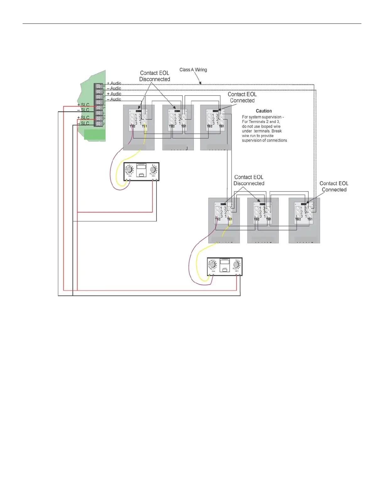
5.3.4 Multi-Phone Jack Audio Circuit in Class A Configuration
For wiring specifications see Section 5.3.1. Figure 5.5 illustrates how to wire the Multi-Phone Jack audio circuit (Class A) and
the SLC for (Class A) configuration. In the Multi-Phone Jack configuration, the maximum mini-monitor contact wiring resis-
tance between the first and the last TR-FPJ must be less that 100 ohms.
.
Figure 5.5 Multi-Phone jack Audio Circuit Wired in Class A
TR-FPJ TR-FPJ TR-FPJ
TR-FPJ TR-FPJ TR-FPJ
TR-FFT