16 PRELIMINARY: TR-FFT Fire Fighter’s Telephone Manual — LS10309-001TR-E:A 04/28/2021
Installation TR-FFT Installation
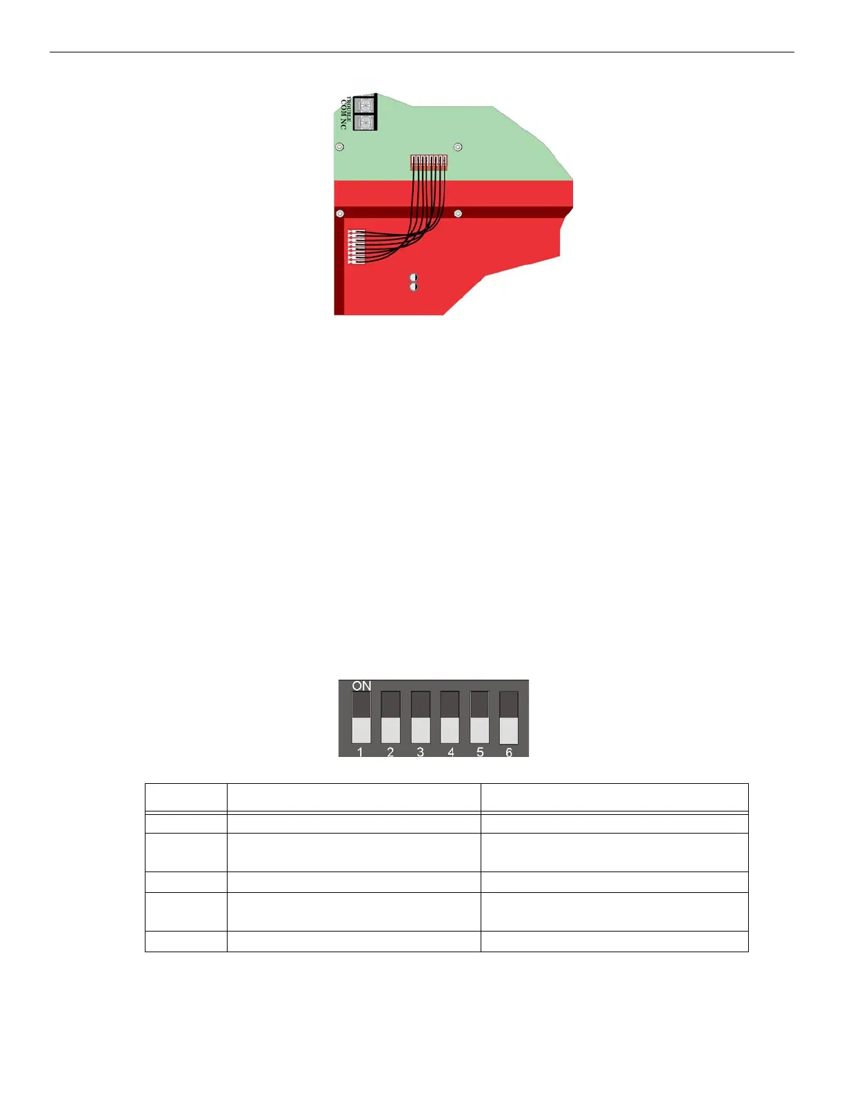
Figure 3.8 Wire Harness Connection from TR-FFT to TR-24Z-EXT Zones 25- 48
7. Restore the power. See Section 3.5.
3.4 TR-FFT Installation
The TR-FFT installation involves the following steps:
• Connect any outputs that will power* the TR-FFT. (See Section 3.5).
• Set the DIP switch ID for the TR-FFT (See Section 3.6.1).
*See Appendix A: for compatible powering devices. For additional information, refer to the Manuals on the website www.tri-
gaglobal.com.
3.5 Power Operation
This Section provides instructions to install the appropriate DC power source.
1. Connect the TR-FFT to the appropriate DC power source. See Section 2.4.1 for power requirements. For compatible
product see Appendix A.
2. Use the on-board DIP switch to assign the configuration setting to the TR-FFT. (See Section 3.6.1).
3.6 DIP Switch Settings on TR-FFT
This Section describes how to configure the DIP switch setting on the TR-FFT.
1. Refer to Section 2.3 to identify the location of the DIP switches on the TR-FFT board.
2. Configure the TR-FFT module by adding it to the System using the JumpStart feature. See Section 6.3 for information on
the JumpStart Operation. Table 3.1 lists the possible DIP switch configurations.
3.6.1 DIP Switch
Figure 3.9 DIP Switch
DIP Switch ON OFF
1 SLC Devices Installed SLC Devices not Installed
2 Trouble PZT Enabled Trouble PZT Disabled
3 SLC Class A Supervision SLC Class B Supervision
4 Phone Circuit Class A Supervision Phone Circuit Class B Supervision
5 First TR-24Z-EXT Expander Board Installed First TR-24Z-EXT Expander Board not Installed
Table 3.1 TR-FFT DIP Switch Configurations