PRELIMINARY: TR-FFT Fire Fighter’s Telephone Manual — LS10309-001TR-E:A 04/28/2021 25
Wiring Requirements for the Audio Telephone Circuit Audio Phone Circuit Installation
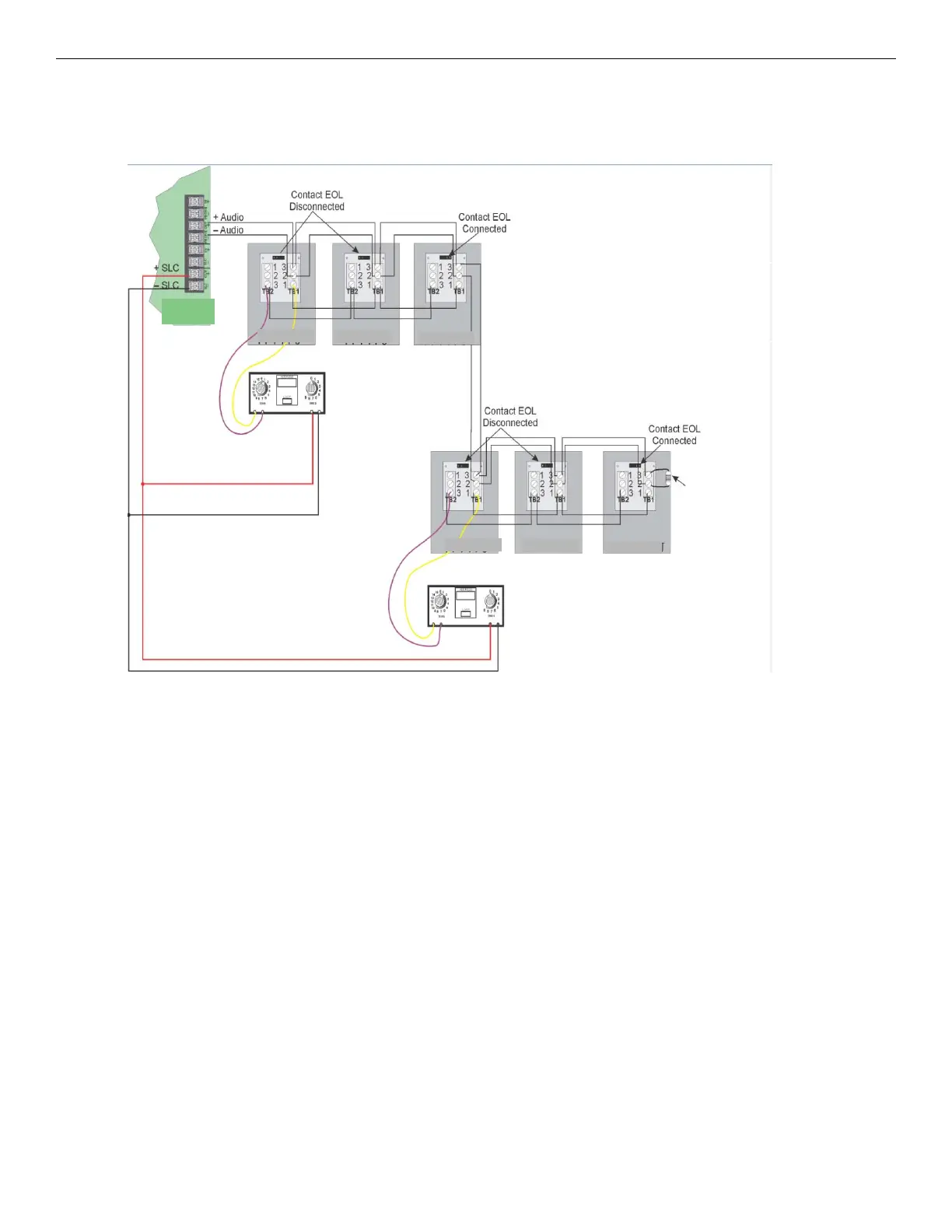
5.3.3 Multi-Phone Jack Audio Circuit Wired in Class B Configuration
For information on the wiring specifications, see Section 5.3.1. Figure 5.4 illustrates how to wire the Multi-Phone Jack Audio
Circuit (Class B) and the SLC for (Class B) configuration. In the Multi-Phone Jack configuration, the maximum mini-monitor
contact wiring resistance between to the first and the last TR-FPJ must be less than 100 ohms.
Figure 5.4 Multi-Phone Jack Audio Circuit Wired in Class B
Caution!
For System Supervision-For Terminals 2 and 3, do not
use looped wire under the terminals. Break wire run to
provide supervision of communications.
4.7K W, 1/2 watt ELR (Install on
the last device for Class B
telephone circuit only).
TR-FFT
TR-FPJ
TR-FPJ
TR-FPJ
TR-FPJ
TR-FPJ
TR-FPJ