PRELIMINARY: TR-FFT Fire Fighter’s Telephone Manual — LS10309-001TR-E:A 04/28/2021 21
Wiring Requirements for SLC Device SLC Device Installation
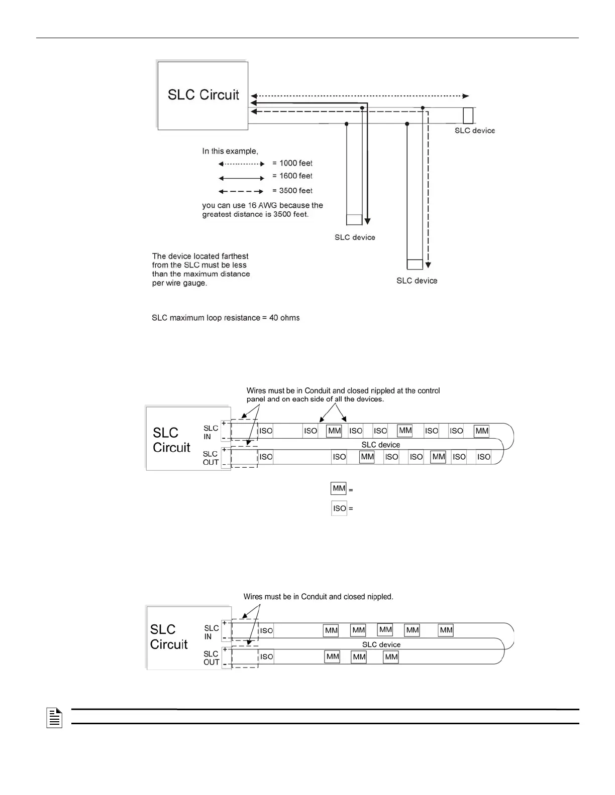
Figure 4.2 Calculating the Wire Run Length for a T-tap
4.3.2 Wiring SLC Devices in (Class A) Configuration
Figure 4.3 illustrates how to wire the SLC loop for Class A installations.
.
Figure 4.3 Class A SLC Configuration
.
Note: A maximum of 20 TR-ISO Modules can
be attached to the TR-FFT.
SLC device, TR-Minimon module
Isolator Device, TR-ISO
NOTE: Class A does not require the use of the isolator modules.There are no T-taps allowed on the Class A SLC loops.