PRELIMINARY: TR-FFT Fire Fighter’s Telephone Manual — LS10309-001TR-E:A 04/28/2021 17
TR-FFT Fire Fighter Telephone Module Connection Installation
3.7 TR-FFT Fire Fighter Telephone Module Connection
The TR-FFT provides the connection for a single Class B or Class A telephone audio circuit. See Section 4 and Section 5 for
examples of audio zone configurations. A monitor module can be used to monitor the connection of the Fire Fighter Telephone
remote handset (TR-RHS) into the TR-FPJ, which is then displayed on the TR-FFT active zone LED during the JumpStart fea-
ture.
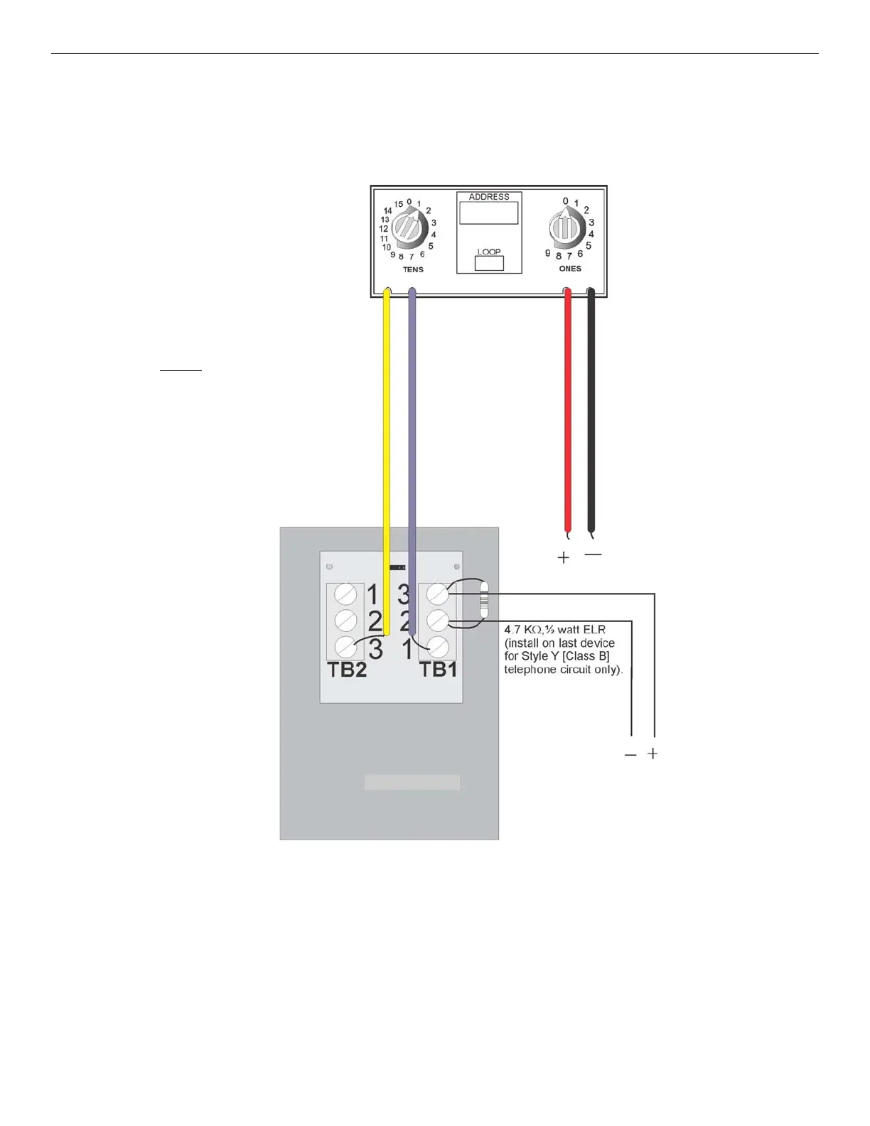
Figure 3.10 Monitor Modules to TR-FFT Connections
3.8 TR-FPJ Installation
The TR-FPJ Firefighter Phone Jack mounts to any of the following:
• a single-gang electrical box (4" x 2-1/8" x 2-½") (10.16cm x 5.54cm x 6.35cm) or
• when the addressable mini-monitor module is installed with it, a deep single-gang electrical box (4" x 2-1/8” x 3-¾”)
(10.16cm x 5.54cm x 9.53cm).
Connect the telephone audio loop between the TR-FPJ and the TR-FFT as detailed in Figure 3.12.
All circuits are power-limited and supervised.
To TR-FFT to SLC Terminal
TB4 Connectors or other
monitor modules.
The wiring between the monitor module
and TR-FPJ is supervised by the monitor
module. A 47K Ω End-of-Line resistor is
built into
the TR-FPJ.
To TR-FFT Phone TB4
phone In/Out + –
connections or other
TR-FPJ’s or TR-
STSR/STSS
TR-FPJ