10
3.5 Hazardous area wiring
If the flow meter has been supplied with the "explosion proof option"
Exd IIB T6, then the following points must be observed:
1) Wiring techniques are to be in accordance with the rules, regulations
and requirements applying to the territory in which the flow meter is being
installed.
The units should only be connected and set up by qualified staff. The
qualified staff must have knowledge of protection classes, regulations
and provisions for the apparatus in hazardous areas.
2) When using shielded cable do not
use the shield as an electrical earthing
conductor. Be sure to isolate the shield / screen from any contact with the
flow meter. The shield / screen is to be connected to the instrument earth
only to protect the transmitted signal from mutual inductive interference.
Electrical earthing lugs are located within the terminal housing cover & on
the underside of the manifold . Use a separate earth within the cable
making sure that the earth conductor does not come in electrical contact
with the cable shield / screen.
3) Use only high temperature cable at the flow meter if the unit is being used
to measure process liquids above 85°C.
4) For Exd explosion proof versions only, the output board has been
assembled into the flow meter terminal housing using a small amount of
potting solution.
If the output board is to be replaced in an Exd version, remove the two
securing screws and then the output board (force will be needed to break
the PC board away from the potting solution). Clear away all remaining
potting solution.
To fit the new output board first fill the recesses in the bottom of the
terminal housing with a small amount of flexible potting solution
( approximately 2ml ) so that there is about 2mm depth of coverage
within the recess slots then fit new output board and allow time for potting
solution to set. Use 3M Scotch guard 2130 potting solution or similar.
3
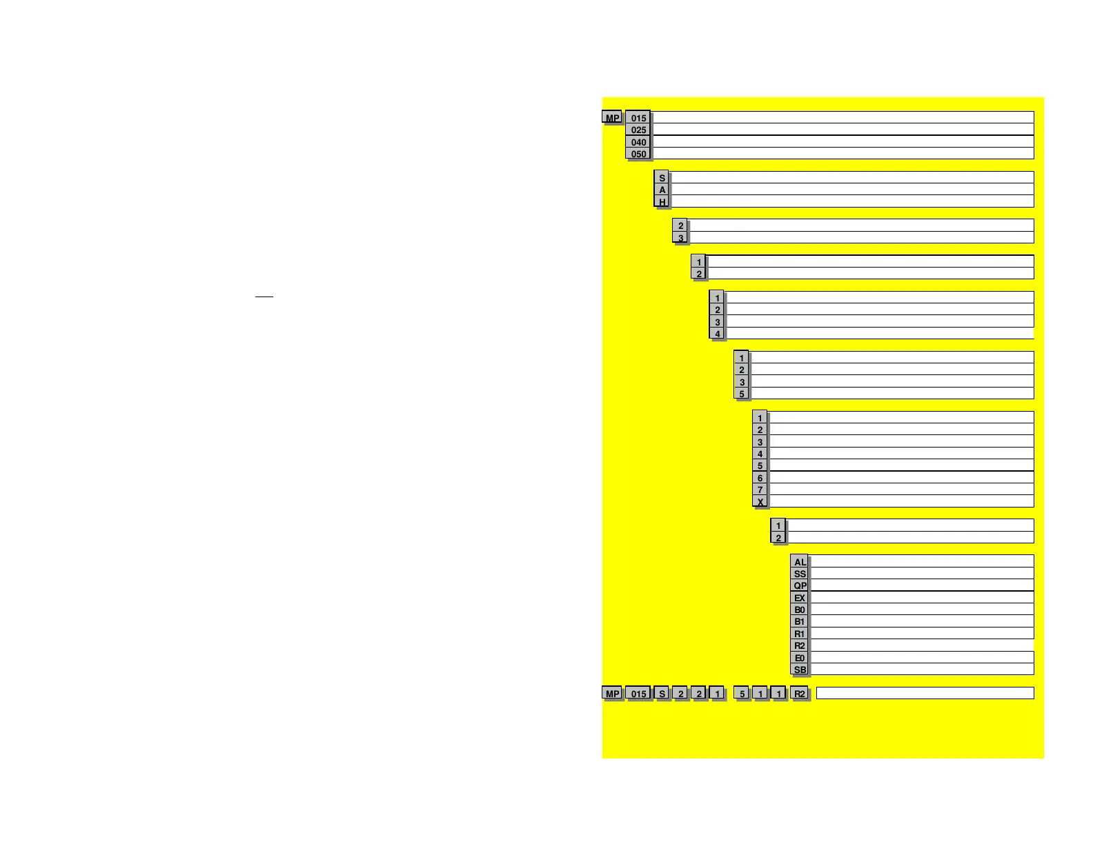
Size
MP 015 1/2"
10~600 l/hr ( 0.04~2.7 USGM )
025 1"
120~3000 l/hr ( 0.5~13.2 USGM )
040 1 1/2"
250~8000 l/hr ( 1.1~35 USGM )
050 2"
700~20000 l/hr ( 3~88 USGM )
Body material
S 316L Stainless Steel
A Aluminium
H
Piston material
2
( polyetheretherkeyt one - 150ºC max.)
3
( carbon filled teflon - 12 0ºC max.)
Partition material
1
for abrasive or low lubricit y liquids
2 316L Stainless Steel
O-ring material
1
2
( Ethylene Propylene Rubber - 150ºC max.)
3
Teflon encapsulated viton
4
( Nit rile - 1 20ºC max.)
Temperature limits
- 1 - 40 to 60ºC
- 2
( no int egral cooling f in )
- 3
( Peek piston & Hall Ef fect out put only )
- 5
( includes int egral cooling f in )
1 BSP-RP female threaded
2 NPT female threaded
3
( ferrules are 1/2" larger than meter size )
4 ANSI-150 RF flanges
5 ANSI-300 RF flanges
6 PN16 DIN flanges
7 PN40 DIN flanges
X
( covered under SB option below )
Cable entries
1 M20 x 1.5mm
2 1/2" NPT
Integral options
AL
SS
Stainless Steel terminal cover
QP
EX
B0
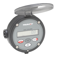
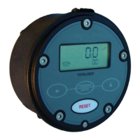
BT10 Tot aliser w ith reset Tot al [not e 2]
B1
(BT10 + scaleable pulse out put)
R1 RT11 Flow Rat e Totaliser [not e 2]
R2
(RT11+ alarms & 4~ 20mA output)
E0 Ecobatch dc batch cont roller [not e 2]
M o d e l N o. E x a m p l e
SB
Special build requirement
(ref. f actory for details)
MP 015 S 2 2 1 - 5 1 1 R2 Special Build No. : SB
Quote special build & serial No's when ordering spares
Notes:
Standard meters are supplied with a GRN terminal cover
( glass re-inforced nylon )
P/No. ACF cooling fin is to be included with integral registers when temp.exceeds 80ºC