Page 18
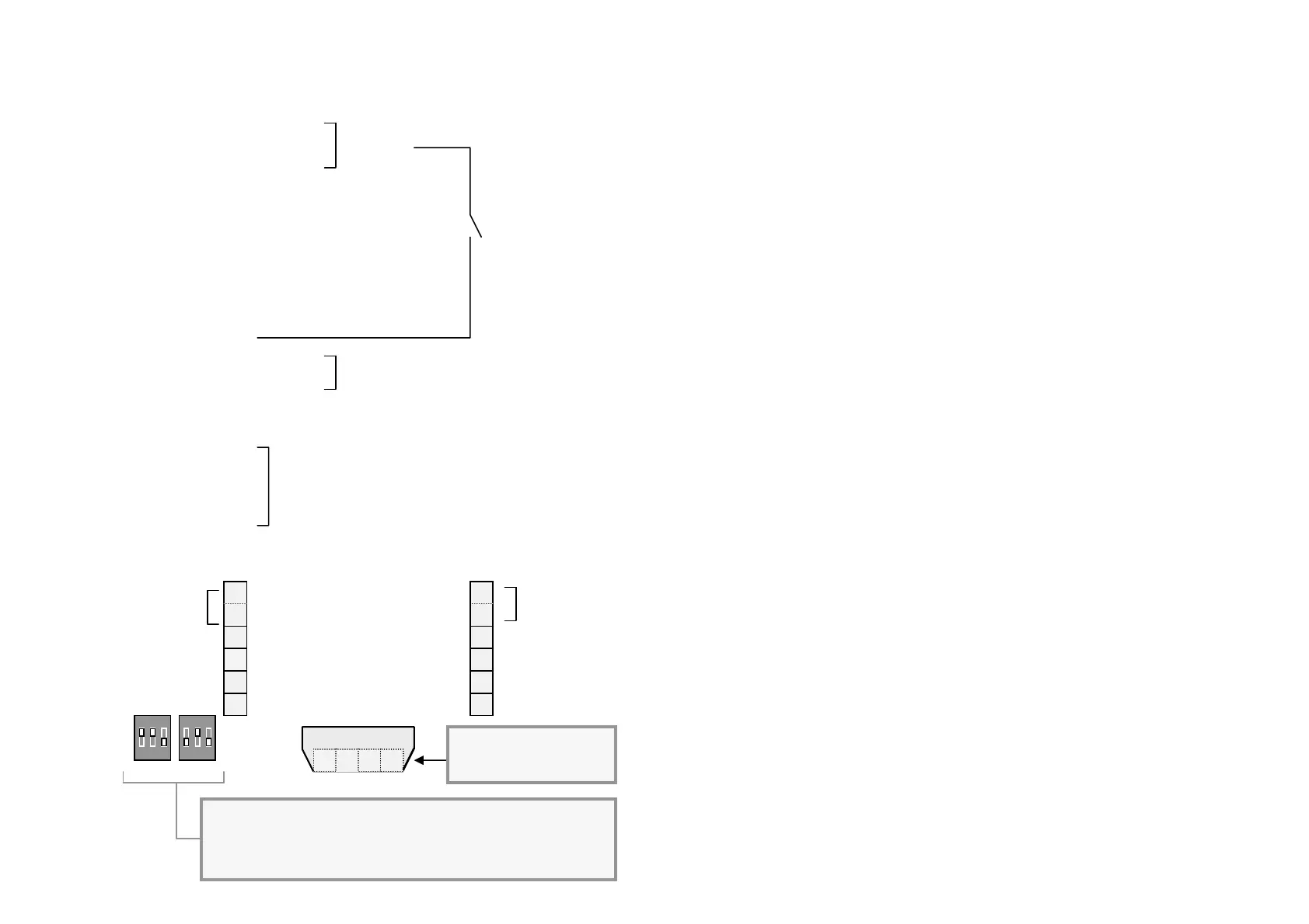
7. TERMINAL DESIGNATION
Terminal layout
Page 3
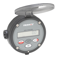
1.2 Specifications
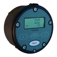
Display : 8 digit alpha numeric LCD characters 9mm ( 0.35 ”) high with
second line sub script text.. 8 digits totalising, 5 digits rate,
3 programmable decimal points with all displays.
Signal Input : Universal pulse/frequency input compatible with Reed switch,
Hall effect, Namur proximity detectors, Voltage pulse and
Coil/sine (20mV P-P min). Input frequency range 0.25~10Khz.
Powering : Basic Rate & Total functions available via an Ultra Lithium battery,
life expectancy can be up to 5~10 years when programmed with
the unique “Ultra Power Save” sleep cycle option. Battery life
reduces when connected with a coil input from turbine flowmeters.
External supply : Regulated & isolated 8~24vdc. or 4~20mA loop powered.
Pulse output : NPN-PNP field effect transistor, scaleable, 100hz x 1A max.
Analog output : Two wire loop powered , 12~24vdc into 750 ohm loop load,
accuracy 0.1% FS, key entry programming of Zero & Span.
Alarm outputs : Two NPN-PNP selectable FET transistors programmable low &
high flow alarms with adjustable deadband (reset differential).
Maximum drive 100mA resistive load. 24VDC max.
Physical : A) IP66 (NEMA 4X) powder coated aluminium enclosure,
B) 3 x M20 or ½ ” NPT female conduit entries,
C) 108mm diameter x 45mm deep x 450g (1lb).
D) Temperature range from -20ºC to +80ºC ( -4ºF to +176ºF).
Configuration
Functions : Flow rate, Accumulated total, Resettable total, scaleable pulse
output & 10 point linearisation, optional Analog & Alarm outputs.
Configuration : Flow chart entry of data with scrolling English text prompts. User
selectable 4 digit PIN number set-up protection. Programmable
rate units & time base for rate, rate dampening, decimal points
and K-factors. All programmed data is E
2
PROM protected.
K-factor range : Eg. Pulses/litre, gallon, lb etc. Programmable range is 0.001~
999999.999 with a floating decimal point during K-factor entry.
Engineering units : Selectable Ltr, gal, m3, kgs, lbs (total). /sec,min,hr or day (rate).
Rate conversion : Enables the rate to be displayed in different engineering units to
that of the totals eg : totals in litres & rate in m3 (cubic metres.)
or : totals in gallons & rate in US barrels (oil).
Power modes : Ultra power save, standby or continuous display selectable.
Dual Inputs options : Programmable for computations A+B, A-B, or A÷B (ratio).
Termina
1 DC power -0v Ground
2 DC power -0v Ground
3 Flow input A ( pulse signals)
4 Flow input B ( pulse signals)
5 4~20mA output (-)
6 4~20mA output (+)
7 High flow alarm output
8 Low flow alarm output
9 Scaled pulse output
10 Remote reset
11 DC power + 8~24Vdc
12 DC power + 8~24Vdc
Common
terminals
Common terminals
Coil flow inputs
A Coil input A
A Coil input A
B Coil input B
B Coil input B
Coil inputs are not
dependant on polarity
Remote reset
(momentary action)
Common
terminals
: On en
a
es 0.01
f ca
acitor for reed switch bounce
SW1
SW2
SW3
: On en
a
es 1 me
ohm
ull u
resiste
: On en
a
es 820 ohm
ull down resiste
Common
terminals
Coil inputs A & B
A
A
B B
6
5
4
3
2
7
8
9
10
11
High flow alarm
Low flow alarm
Scaled pulse output
Remote reset
+ 8~24VDC supply
- 4~20mA output
+ 4~20mA output
Flow input B
Flow input A
-0V Ground
121
-0V Ground + 8~24VDC supply
ON
1 2 3
A B
ON
1 2 3
Flow inputs
A & B
DIP switches
Note: Coil input board must
be removed if using flow
inputs at terminals 3 or 4