2
1.0 OVERVIEW
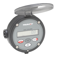
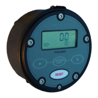
The Trimec Multipulse flow meter is a precision machined positive displacement
flow meter capable of measuring a wide range of liquid flows
and viscosities irrespective of their chemical or physical properties.
Each flow meter is manufactured from 316L stainless steel, suitable for a broad
selection of chemicals. PVC and Aluminium flow meters are available in certain
sizes for specific applications.
A flameproof option is available on all the stainless steel and aluminium models.
The Multipulse can also be used within hazardous areas when connections are
made across the reed switch output in conjunction with an approved electrical
safety barrier.
Typical I.S. barriers include
:
- MTL Model 3011 or 3012
- P & F Model KHD2-OT1-Ex1
11
4.0 MAINTENANCE
4.1 Dismantling
The Multipulse has been constructed in such a way that the flow meter
manifold need not be disturbed when servicing the flow meter in-situ.
Isolate the flow meter from its source of supply and allow any excess liquid
to drain out. Remove the cap screws located around the flow meter body and
gently lever the body off the manifold at the slots provided on either side.
Caution
: Lever action needs to be even on both sides so as to avoid 'walking'
the body from side to side. This inturn could damage the ceramic partition or
piston spigot, for this reason ceramic partitions are not covered by warranty.
4.2 Inspecting
Lift the piston out of the flow meter and inspect for signs of wear or damage.
Ensure that no particles are impinged into the piston walls and remove any
foreign material inside the flow meter. Inspect the O-ring and centre bearing
for damage. Replace any suspect parts.
4.3 Re-assembling
Replace the piston and rotate it by hand to ensure freedom of movement.
Align the slot in the body with the partition plate and firmly press the body evenly
onto the manifold. A smear of lubricant on the O-Ring will assist. CAUTION, the
partition plate is rectangular on all models & must be assembled with the long
face to the centre boss of the manifold.
5.0 CLEANING IN-SITU
When a system is to be cleaned in place (CIP), sterilised or purged without
removal of the flow meter, it is advisable to provide a by-pass around the
flow meter to avoid damaging the piston unless the following recommendations
are adhered to.
1) The cleaning fluid must be compatible with the piston and O-ring materials.
2) During steam sterilising ensure the steam temperature does not exceed the
maximum operating temperature of the flow meter.
3) The velocity of the steam must be carefully restricted to ensure the velocity
of the piston does not exceed the equivalent of maximum flow rate.
The same restrictions apply when purging with air or gas.