10
3.5 Hazardous area wiring
If the flow meter has been supplied with the "explosion proof option"
Exd IIB T6, then the following points must be observed:
1) Wiring techniques are to be in accordance with the rules, regulations
and requirements applying to the territory in which the flow meter is being
installed.
2) When using shielded cable do not
use the shield as an electrical earthing
conductor. Be sure to isolate the shield / screen from any contact with the
flow meter. The shield / screen is to be connected to the instrument earth
only to protect the transmitted signal from mutual inductive interference.
Electrical earthing lugs are located within the terminal housing cover & on
the underside of the manifold . Use a separate earth within the cable
making sure that the earth conductor does not come in electrical contact
with the cable shield / screen.
3) Use only high temperature cable at the flow meter if the unit is being used
to measure process liquids above 85°C.
4) For Exd explosion proof versions only, the output board has been
assembled into the flow meter terminal housing using a small amount of
potting solution.
If the output board is to be replaced in an Exd version, remove the two
securing screws and then the output board (force will be needed to break
the PC board away from the potting solution). Clear away all remaining
potting solution.
To fit the new output board first fill the recesses in the bottom of the
terminal housing with a small amount of flexible potting solution
( approximately 2ml ) so that there is about 2mm depth of coverage
within the recess slots then fit new output board and allow time for potting
solution to set. Use 3M Scotch guard 2130 potting solution or similar.
3
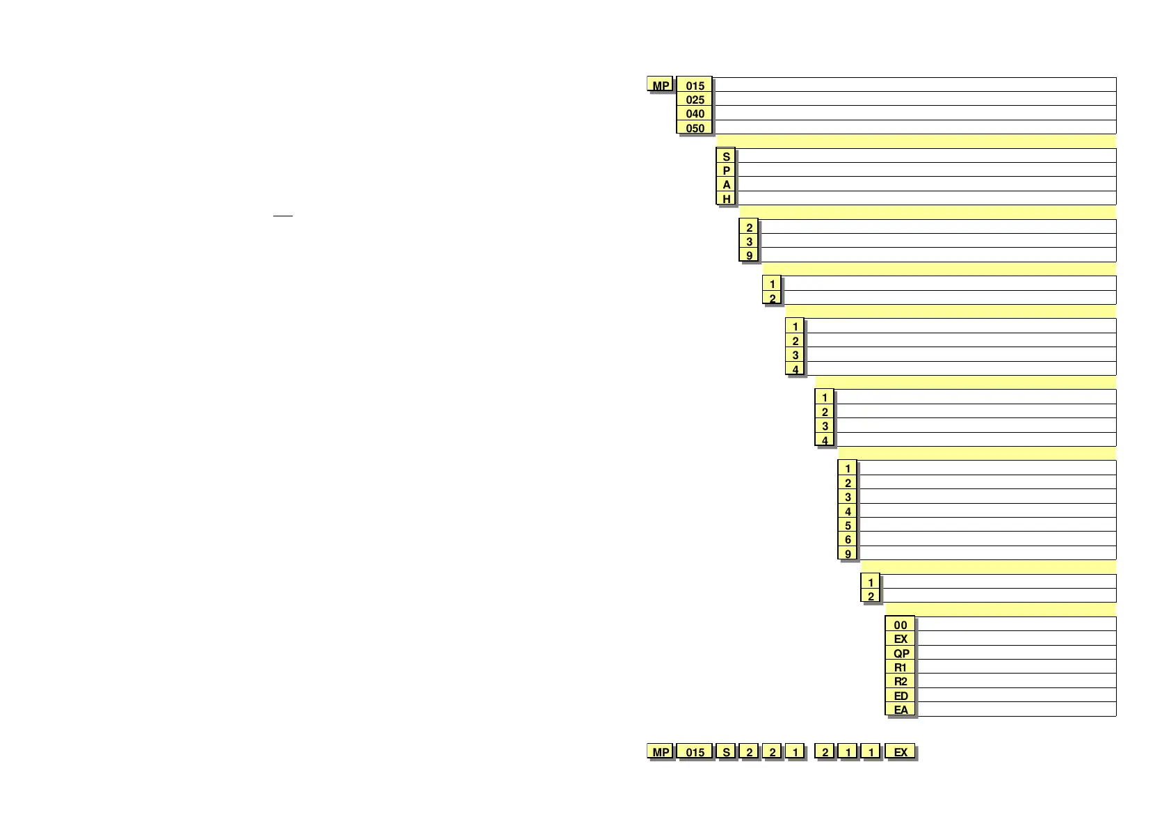
1.1 Model Number designation
MP 015
1/2"
15mm
025
1"
25mm
040
1 1/2"
40mm
050
2"
50mm
|
Body material
|
S
316L Stainless Steel
|
P
UPVC
|
A
Aluminium
|
H
High Pressure 316L Stainless Steel
||
Piston material
||
2
PEEK
||
3
CFT
||
9
Special
|||
Partition material
|||
1
Ceramic ( for abrasive applications )
|||
2
316L Stainless Steel
| |||
O-ring material
| |||
1
Viton (standard)
| |||
2
EPR -
Et h
lene Pro
lene Rubbe
| |||
3
Teflon
| |||
4
Buna-N (Nitrile)
| ||||
Temperature ranges
| ||||-
1
- 40 to 60 deg. C
| ||||-
2
10 to 120 deg C
| ||||-
3
60 to 150 deg C (Hall Effect output only)
| ||||-
4
0 to 40 deg C ( MP025P only )
| |||| |
Process connections
| |||| |
1
BSPP female
| |||| |
2
NPT female threaded
| |||| |
3
*Tri-clamp-hygienic
| |||| |
4
ANSI 150 RF flanges
| |||| |
5
ANSI 300 RF flanges
| |||| |
6
ANSI 600 RF flanges
| |||| |
9
Customer nominated connections
| |||| ||
Cable entries
| |||| ||
1
M20 x 1.5mm
| |||| ||
2
1/2" NPT
| |||| |||
Integral options
| |||| |||
00
No options
| |||| |||
EX
Explosion proof
| |||| |||
QP
Quadrature pulse output (Hall only)
| |||| |||
R1
RT11 (scaleable pulse output)
| |||| |||
R2
RT12 (RT11+ 4-20mA & alarms)
| |||| |||
ED
DC powered ecobatch batcher
| |||| |||
EA
AC-DC powered ecobatch batcher
| M o d e l N o. E x a m
l e |
| |||| ||| |
MP 015 S 2 2 1
-
211 EX