4
5. Features
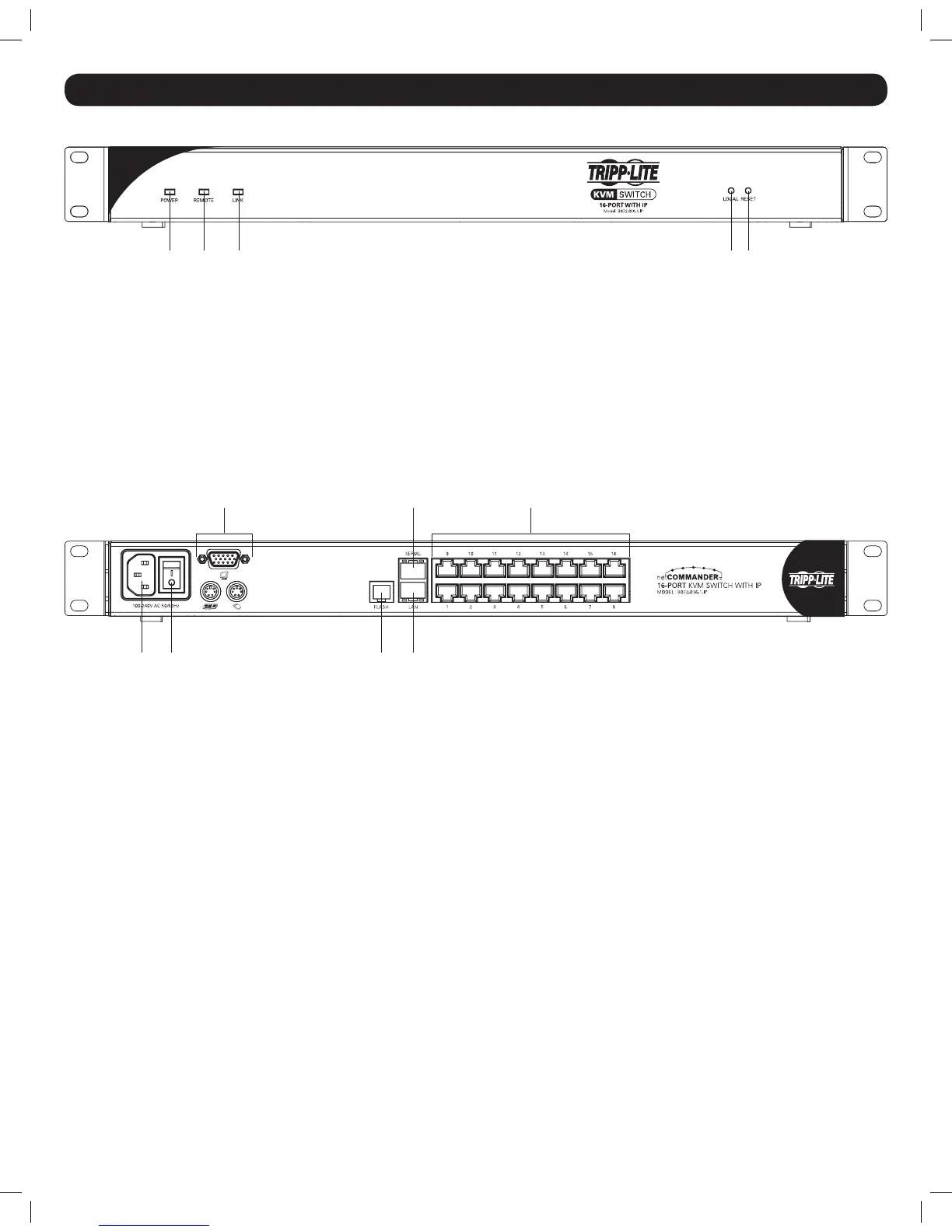
Front View
1. Power LED – Illuminates to indicate that the KVM switch is receiving power.
2. Remote LED – Illuminates to indicate that the KVM switch is being remotely accessed.
3. Link LED – Illuminates to indicate that the KVM switch is connected to a network, and can be remotely accessed.
4. Local Button – When a remote user has control of the KVM, press this button to disconnect their session and restore control to the local console.
5. Reset Button – Press and hold this button for 7 or more seconds to perform a system reset.
Back View
1. C14 Power Inlet – Connect the included power cord to the unit here, and then plug it into a Tripp Lite Surge Suppressor, Power Distribution Unit
(PDU), or Uninterruptible Power Supply (UPS).
2. On/Off Switch – Turn the power to the KVM switch on/off using this switch.
3. Console Ports – Connect a VGA monitor, and PS/2 keyboard and mouse to the KVM here.
4. Flash Port – Connect the included RJ11 to DB9 cable to the KVM here when performing an upgrade to the KVM’s mainboard and local OSD
rmware. The rmware for the KVM’s IP functionality is upgraded over the network.
5. LAN Port – Connect the KVM to a 10/100Mbps network using this port.
6. Serial Port – This port currently serves no functional purpose. It is included for future functionality upgrades.
7. Computer Ports – Connect the KVM to Server Interface Units (SIUs), which in turn connect to computers/servers, via these RJ45 ports.
1
2
3
4
5
1
2
3
4
5
6
7
6
7
1
2
3
4
5
1
2
3
4
5
201204111 93-2769.indd 4 8/2/2012 10:15:54 AM
 Loading...