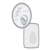
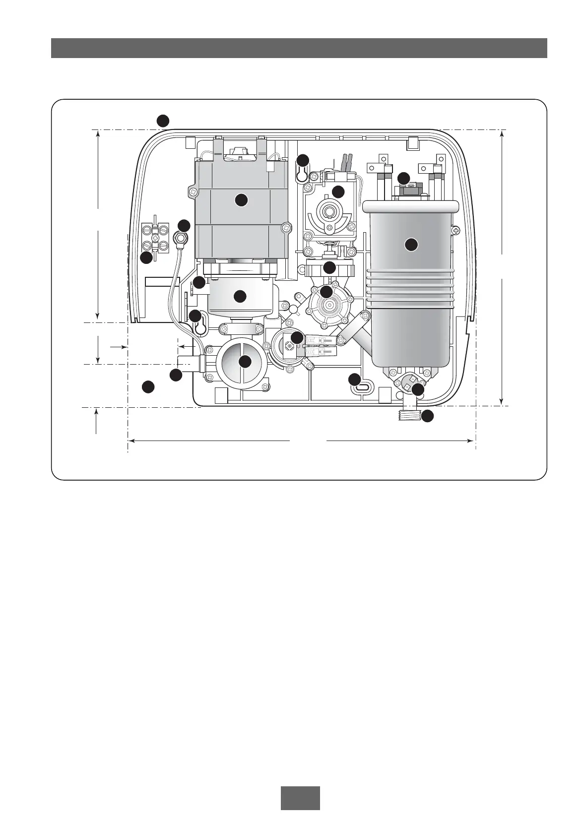
Fig.1
Main components (fig.1)
1 Top pipe/cable entry
2 Motor assembly
3 Pump assembly
4 Bleed screw
5 Wall screw fixing
6 Power selector assembly
7 Thermal cut-out (main)
8 Terminal block
9 Can and element assembly
10 Area for bottom and back pipe/cable entry
11 Pressure switch
12 Temperature valve
13 Solenoid valve
14 Earth connection
15 Inlet pipe
16 Filter
17 Thermal cut-out (outlet)
18 Outlet pipe
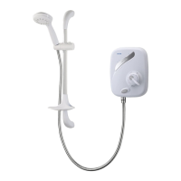
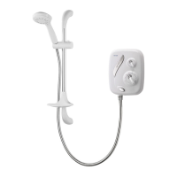
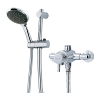
Pack contents
Shower unit
Riser rail
Sprayhead
Sprayhead holder
Riser rail brackets
Hose
Soap dish
Fixing screws and plugs
Compression elbow
Two year and extended guarantee options
Note: Not all wires have been depicted for reason of clarity.
KEY TO MAIN COMPONENTS
 Loading...