8
Aspirante pumped electric
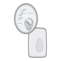
Fig.7
Fig.8
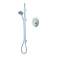
FITTING THE SHOWER TO THE WALL
Note: The control knobs are an integral part of
the cover – DO NOT attempt to remove them.
IMPORTANT: The unit must be mounted on
a flat surface which covers the full width and
length of the backplate. It is important that
the wall surface is flat otherwise difficulty
may be encountered when fitting the cover
and subsequent operation of the unit may be
impaired.
Unscrew the two top and two bottom retaining
screws (fig.7) and lift the cover from
backplate.
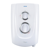
If a top entry is required for the water pipe,
then remove the top cut-out in the backplate
(fig.8).
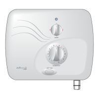
If a bottom entry is required for the cold water
pipe, then a hole will need to be cut out of the
cover (fig.9).
If entry is from the back, the nut of the
compression fitting will be partially behind the
surface of the wall (fig.10). This area must be
left clear when plastering over the pipework to
make the nut accessible for future adjustments.
Note: Make sure the hole in which the pipe
enters through the wall is filled in completely in
order to prevent any possible ingress of water
into the cavity area (fig.10).
Note: Deviations from the designated entry
points will invalidate product approvals.
After choosing the site for the shower, use the
backplate as a template and mark the three
fixing holes (fig.11).
Drill and plug to suit the fixing screws supplied.
(The wallplugs provided are suitable for most brick
walls – use an appropriate masonry drill, but if the
wall is plasterboard or a soft building block, use
special wallplugs and a suitable drill bit).
Screw the two upper fixing screws into position
leaving the base of the screw heads protruding
6mm out from the wall.
Hook the backplate over the top screws and fit
the lower fixing screw into position.
Fig.9
 Loading...