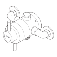
Thermostatic shower pole
5
Isolating switch or
pull cord switch
(both fused at 3A)
Hot water
cylinder
Shower
pole
Service
valve
Cold supply
Hot supply
Alternative
supply
Cold
water
mains
supply
Ring main
Drain
valve
Gate
valve
Service
valve
Other
draw-offs
Stop valve
Cold water
cistern
Pump
Minimum head
Flow
Return
Boiler
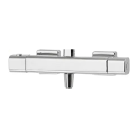
Blender
valve
Cold mains supply
Hot
water
Stop tap
Expansion
vessel
Pressure
reducing valve
Service
valves
Shower pole
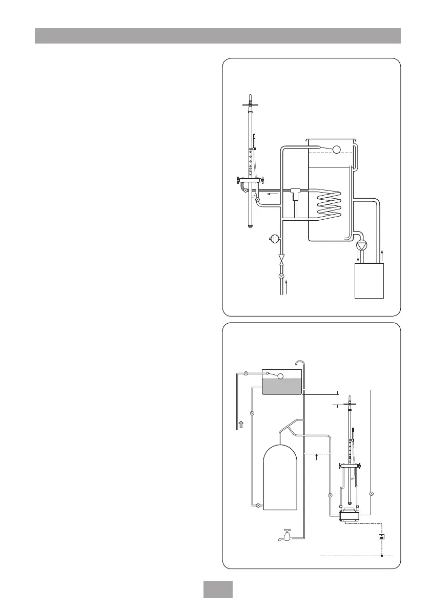
Fig.4 (diagrammatic view – not to scale)
Fig.5 (diagrammatic view – not to scale)
c) Mains pressurised thermal store
systems
(fig.4)
Packages of this type, fitted with a tempering
valve (blender valve) can be used. A drop tight
pressure reducing valve MUST be fitted if the
supply pressures exceed 5 bar running.
An expansion vessel (shown in fig.4) MUST be
fitted, and regularly maintained, to make sure
the unit is not damaged by excess pressures.
This may already be installed externally or
internally within the thermal store (check with
thermal store manufacturer).
d) Pumped gravity fed systems (fig.5)
The shower MUST be fed from a cold water
cistern and hot water cylinder providing
nominally equal pressures.
The mixer unit may be used with a gravity
fed system with a pump to boost pressures
as shown. There will be a minimum head
requirement which will be specified in the
installation and operation instructions supplied
by the pump manufacturer.
 Loading...