 Loading...
Do you have a question about the Triton Omnicare and is the answer not in the manual?
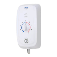
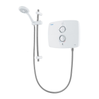
| Type | Electric Shower |
|---|---|
| Temperature Control | Thermostatic |
| Water Connection | 15mm compression |
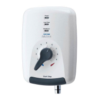
| Start/Stop Button | Yes |
| Material | Plastic |
| Finish | White |
| Installation Type | Wall Mounted |
| Warranty | 2 years |
| Water Entry Points | Bottom |
| Cable Entry Points | Bottom Entry |
| Approvals | WRAS |