12
ASSEMBLY STEPS
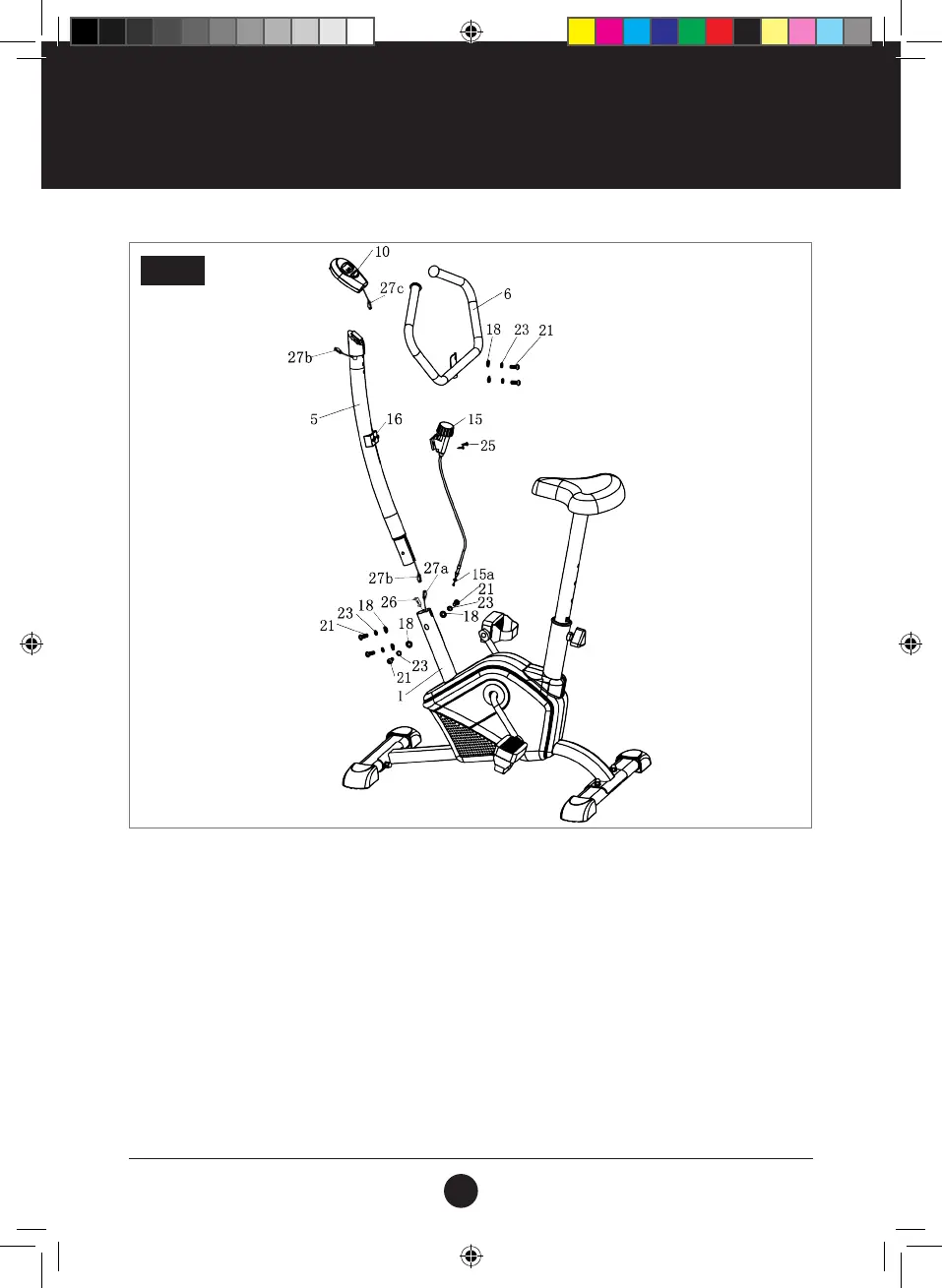
STEP 3: TENSION CONTROL
Connect Tension Controller (15) to Tension Control Base (16) using 2 Tapping Screws (ST 4.2 x 16) (25). Connect the
Tension Control Cable (15a) to the Tension Cable Connection (26). Connect Console Cable (27a) with the end of Cable
(27b). Carefully insert Handlebar Support Assembly (5) into the Main Frame (1) using 4 Bolts (M8 x 20) (21),
4 Spring Washers (Ø8) (23) and 4 Arc Washers (Ø8) (18).
Connect Handlebar (6) to Handlebar Support (5) using 2 Washers (Ø8) (18), 2 Spring Washers (Ø8) (23) and 2 Bolts
(M8 x 20) (21). Connect Cable (27b) with Cable (27c). Connect Console (10) to Console Base (9).
To adjust the tension, use the Tension Controller (15) to achieve the required tension level.
To adjust Saddle height, use Tension Knob (13).
STEP 3
#19M05T013 Apex 100 Bike UM V2.indd 12 15/07/2019 14:05
 Loading...