11
ASSEMBLY STEPS
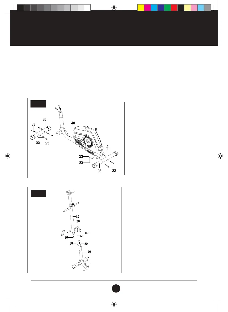
STEP 1:
Attach the Front Stabiliser (35) and the Rear
Stabiliser (36) to the Main Frame (40) with
Carriage Bolt (M8 X 60) (33), Arc
Washers (D8 X ø20 X 2 X R30 (22), Domed
Nut (M8) (23).
STEP 1
STEP 2:
Connect the Wire (16) into the Sensor (38), using
the Tension Control (53) and Tension Wire (39).
Attach the Upright Post (15) into the Main
Frame (40) with Bolt (M8 x 16 x S6) (26) and the
Arc Washer (D8 X ø20 X 2 X R30) (22).
INSTRUCTIONS FOR ASSEMBLY
• Before assembling make sure that you will have enough space around the item.
•
Use the supplied parts and hardware for the assembly.
•
Before assembling, please check whether all the required parts have been supplied as per the exploded
drawing on the opposite page.
STEP 2
#20M01T010 Trojan Orbit 250 Elliptical.indd 11 2020/03/25 4:18 PM
 Loading...