12
ASSEMBLY STEPS
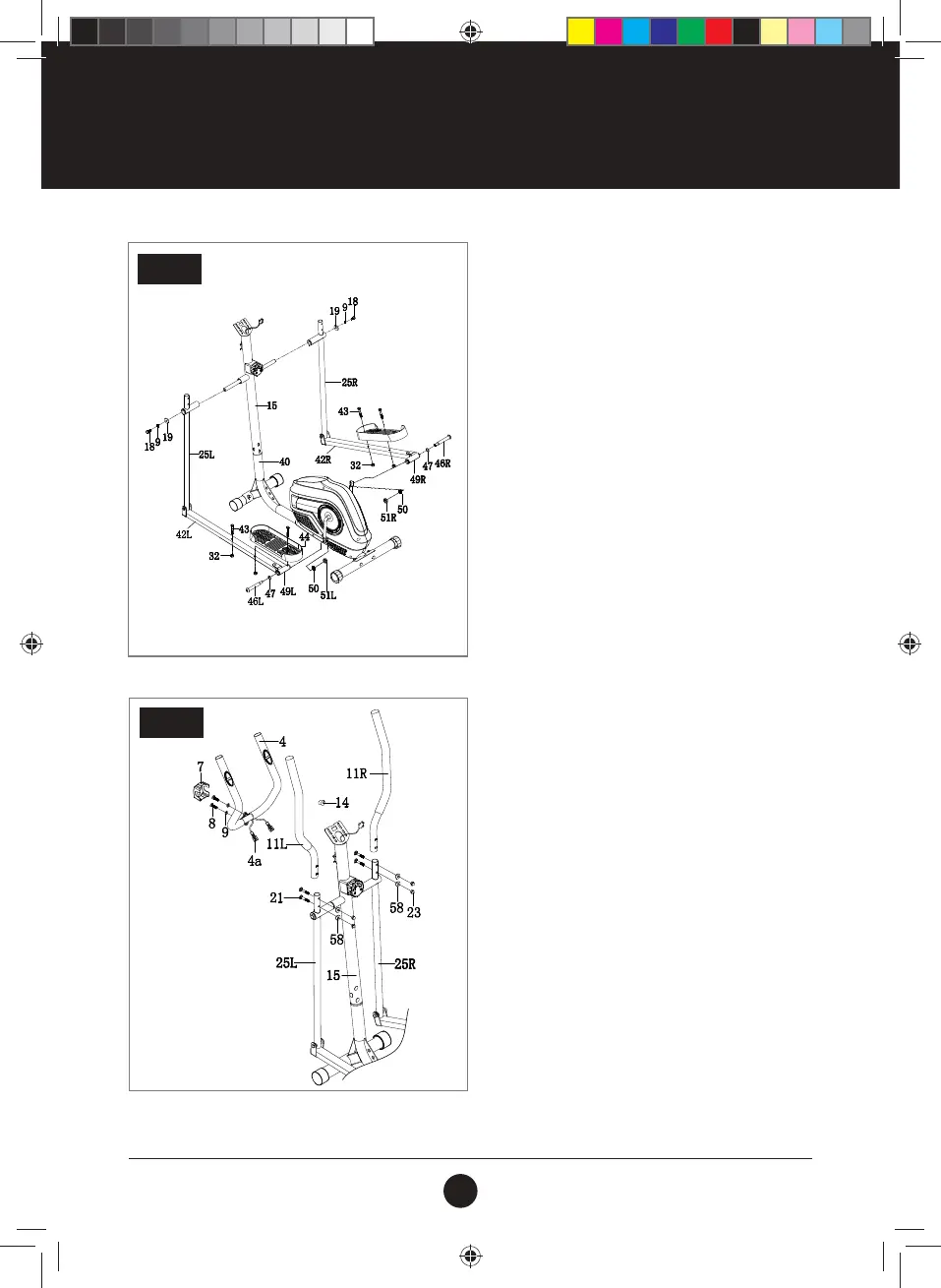
STEP 3:
Insert the Lower Handlebar (25 L/R) into the
Upright Post (15) with the Bolt (M8 x 16) (18), Spring
Washer (D8) (9) and Washer (D8 X ø32 X 2) (19).
Attach the Pedal Tubes (42 L/R) (42) with the
Pedal Crank using Bolt (L/R) (1/2’’) (46), Spring
Washer (1/2’’) (50), and Nylon Nut (L/R) (1/2’’) (51).
Install the Pedal (44) onto the Pedal Tube (42L/R) (42)
using the Bolt (M10 X 45) (43) and the Nylon
Nut (M8) (32).
STEP 3
STEP 4:
Connect the Sensor, Install the Middle
Handlebar (4) into the Upright Post (15)
using Bolt (M8 x 30) (8) and the Spring
Washer (D8) (9).
Insert the Handlebar (11 L/R) (11) into the Lower
Handlebar (25 L/R) (25) using Bolt (M8 x 40) (21),
and Arc Washer (D8 X ø16 X 1.5 X R30) (58) and
Domed Nut (M8) (23).
STEP 4
#20M01T010 Trojan Orbit 250 Elliptical.indd 12 2020/03/25 4:18 PM
 Loading...