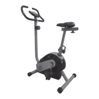
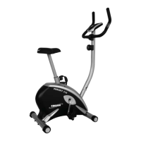
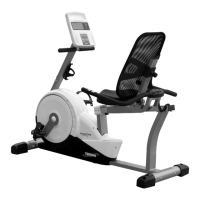
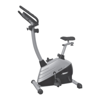
ASSEMBLY STEPS
STEP 3: HANDLEBAR POST INSTALLATION
• Remove four M8 x 15 Hexagon Bolts (24), two Ф8 x Ф20 x 1.5 Arc Washers (71), two Flat Washers
Ф8 x Ф20 x 1.5 (72) and four Ф8 Spring Washers (73) from the tube of Main Frame (1). Remove bolts
with S6 Allen Wrench provided.
• Connect the Sensor Wire (26) from the Main Frame (1) to the Extension Sensor Wire (59) from the
Handlebar Post (3).
• Put the Cable end of resistance cable of Tension Control Knob (7) into the cable lock of Tension Cable
(54). Pull the resistance cable of Tension Control Knob (7) up and force it into the slot of metal bracket
of Tension Cable (54). Insert the metal tting on the resistance cable of Tension Control Knob (7) into
the hole at the end of slot in the metal bracket of Tension Cable (54).
• Connect the resistance cable of Tension Control Knob (7) to the Tension Cable (54).
• Insert the Handlebar Post (3) onto the tube of Main Frame (1) and secure with four M8 x 15 Hexagon
Bolts (24) two Ф8 x Ф20 x 1.5 Arc Washers (71), two Flat Washers Ф8 x Ф20 x 1.5 (72) and four Ф8
Spring Washers (73) that were removed. Tighten bolts with S6 Allen Wrench provided.
STEP 3
TOOL:
Allen Wrench (S6)
 Loading...