ASSEMBLY STEPS
STEP 03
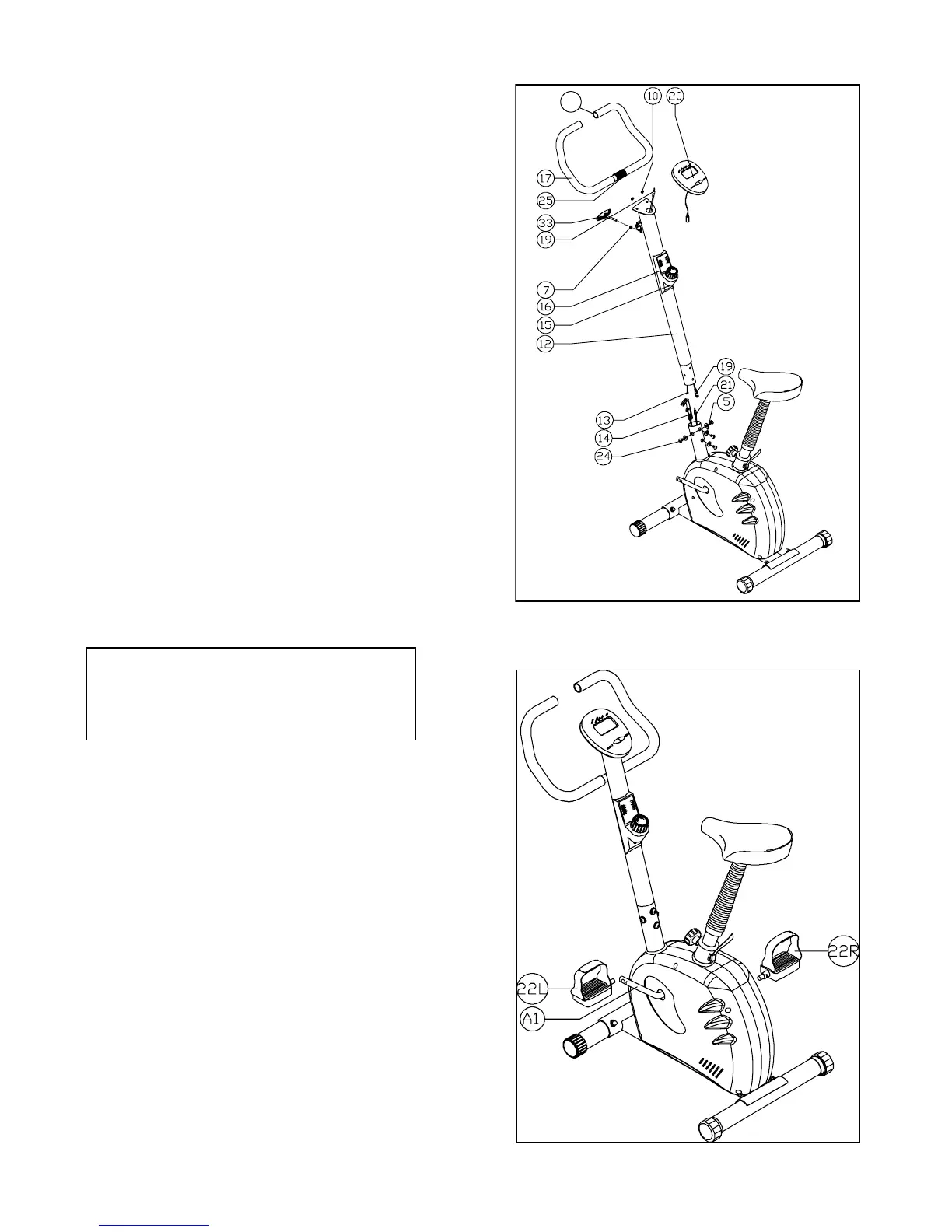
• RemovetheScrews(24)andWashers(5)fromthe
Main Body (1).
• ConnectthetwoendsoftheTensionControlCable
(13) and (14).
• ConnectthetwoendsoftheComputer
Wire (19) and Sensor Wire (21).
• SlidetheHandlebarPost(12)intotheMainBody(1)
and secure into place using 4 Screws (24) and
4 Washers (5) provided.
• PulltheTensionStrapuntilitishandtightandlockit
into place using the small clasp.
• PlacetheHandlebar(25)intotheHandlebar
BracketonthefrontofHandlebarPost(12).
• TightentheT-knob(33)andWasher(7)tolockthe
Handlebar (25) into place.
• ConnecttheComputerWire(19)totheComputer
(20).
• SecuretheComputer(20)with2screws(10)tothe
holder on the top of Handlebar Post (12).
• SlidebothFoamGrips(17)ontotheHandleBar(25),
then insert the 2 End Caps (23A) into the Handle Bar
(25) ends.
STEP 04
• FitthePedal(22L)marked“L”totheleftside
ofthebike,andthePedal(22R)marked“R”to
therightsideofthebike,viewedfromtheriders
seated position.
• Tightenbothsidesofpedalsusingspanner
provided.
• PleasenotethattheRightPedal(22R)needstobe
screwedinaclockwisedirection.
• TheLeftPedal(22L)needstobescrewedina
anti-clockwisedirection.
• Makesurethatallboltsandscrewsaresecure.
Theexercisebikeisnowreadytouse.