13
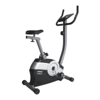
STEP 5: HANDLEBAR ASSEMBLY
Remove 2 Hexagon Bolts (M8 x 15) (24) and
2 Curve Washers (Ø8) (37) from the Handlebar
Post (3). Remove the Bolts with the Allen
Wrench (S6) provided.
Insert the Hand Pulse Sensor Wires (53)
into the hole of the Handlebar Post (3) and
then pull them out from the top end of the
Handlebar Post (3).
Attach the Handlebar (2) onto the Handlebar
Port (3) with 2 Hexagon Bolts (M8 x 15) (24)
and 2 Curve Washers (Ø8) (37) which were
originally removed. Tighten the Bolts with the
Allen Wrench (S6) provided.
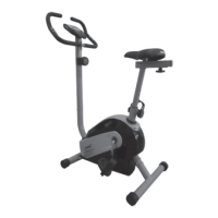
STEP 6: CONSOLE ASSEMBLY
Insert the Extension Sensor Wire (59) and Hand
Pulse Sensor Wires (53) into the hole of Console
Holder (64). Slide the Console Holder (64) onto
the top of Handlebar Post (3), and connect the
Extension Sensor Wire (59) and Hand Pulse
Sensor Wires (53) with the wires from the
Console (10).
Attach the Console (10) to the
Console holder (64).
ASSEMBLY STEPS
STEP 5
STEP 6