ID5000, XR5000 Level 1 Service Manual
Issue 4, 8/2017 33
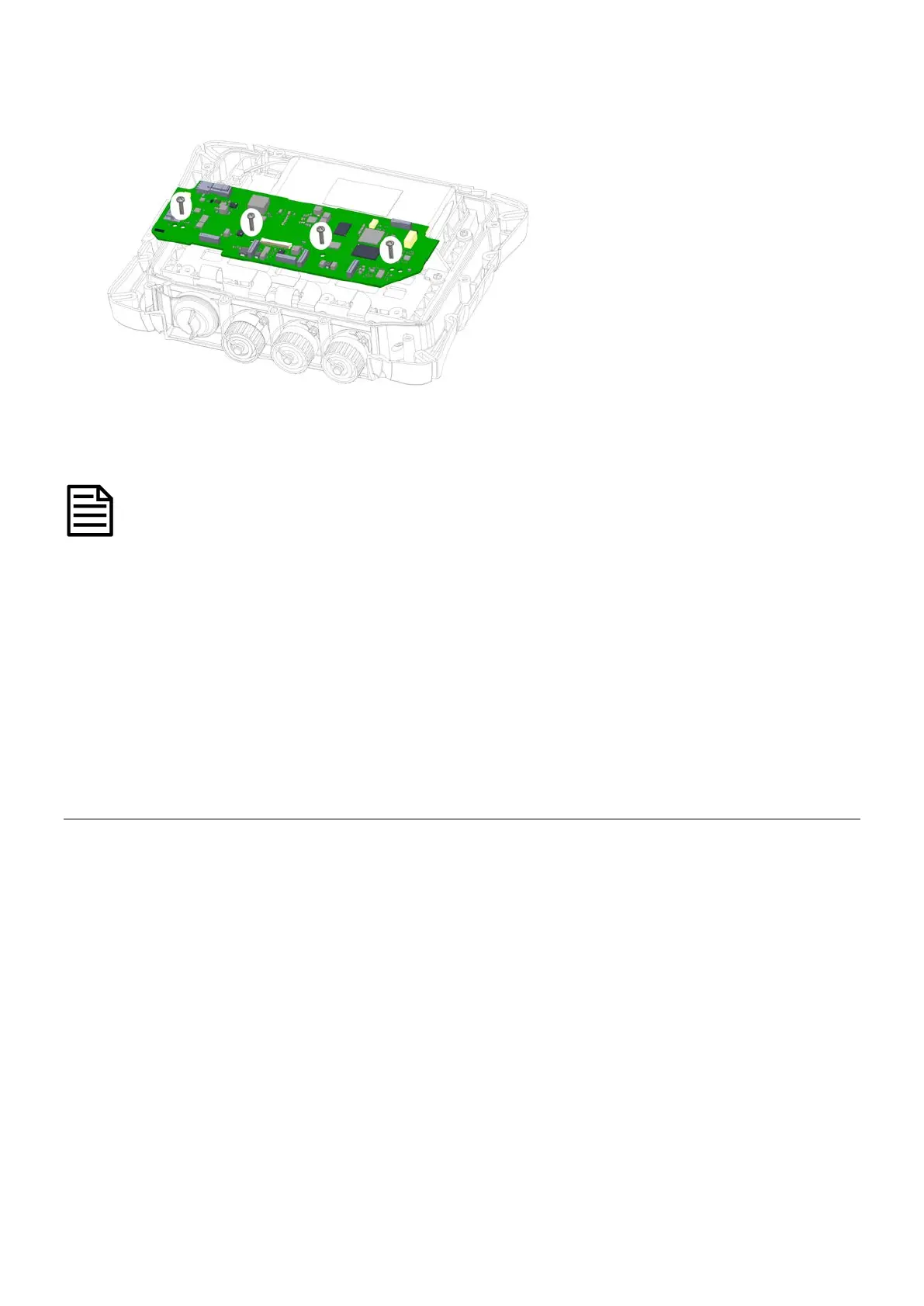
4 Unscrew the four retaining screws holding the PCA to the case front.
screws
5 Lift and slide the PCA out of the cradle.
The PCA is factory pre-set to ID5000 or XR5000. If fitting a replacement PCA, ensure that the spare part matches
the model being serviced.
1 Fit the PCA in place by sliding the board under the clips and positioning the locating holes over the locating pins on the
cradle.
2 Ensure that the LCD FPC is correctly positioned between the PCA and cradle so that it can be re-connected to its connector
on top of the PCA.
3 Screw in the four retaining screws to fasten the PCA to the case front (see
Figure 17: PCA retaining screws
). If available,
use a torque limited screwdriver set to 0.5 Nm (4 lbf-in).
4 Connect the six FPCs and the battery (see
Figure 16: PCA connections
).
5 Refit the case back (see page 25).
6 Refit the rubber corner bumpers (see page 23).
Replacing the cradle
1 Remove the rubber corner bumpers (see page 23).
2 Remove the indicator case
back (see page 25).
3 Remove the battery (see page 28).
4 Remove the PCA (see page 32).