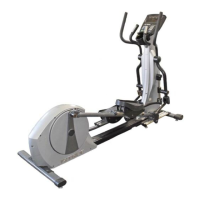
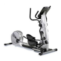
CHAPTER 2: ASSEMBLY INSTRUCTIONS
Truefitness.com / 800.426.6570 / 636.272.7100 12
TREADMILL ASSEMBLY STEPS (continued):
Important Display Specification:
Verify on customer product order what type of display will be installed on this treadmill.
Listed below are the four display options for these series of treadmills.
Find the correct Display Option for assembly and follow frame cable routing (step 3) directions for either section 3-2A or
3-2B and for console cable connections (step 11) follow section 11A or 11B
NOTE: Cables will be labeled near their connector with identifying names such as those listed in BOLD TEXT throughout
these instructions.
NOTE: See TCS400 Treadmill Frame Cable Connection Table below for 120V or 230V cable connections summary.
TCS400 TREADMILL FRAME CABLE CONNECTONS 110V
Pedestal Cable or Power Supply
AUXILIARY POWER SUPPLY
DISPLAY CONSOLE.
DISPLAY CONSOLE. CUSTOMER
N/A N/A
YES = MAKE CABLE CONNECTION NO = DO NOT CONNECT N/A = NOT APPLICABLE
TCS400 TREADMILL FRAME CABLE CONNECTONS 220V
Pedestal Cable or Power Supply
REQUIRED- INSTALLED IN
TREADMILL FROM FACTORY
REQUIRED- INSTALLED IN
TREADMILL FROM FACTORY
N/A N/A
YES = MAKE CABLE CONNECTION NO = DO NOT CONNECT N/A = NOT APPLICABLE
NOTE: Reference Wiring Schematic and Frame Cable Routing Diagram contained in these assembly instructions. You
may remove from packet to aid in assembly but if you remove we recommend you retain these diagrams with the
instructions for future reference.