EasyManua.ls Logo

TSC TC310 Series

TSC TC310 Series
41 pages
To Next Page IconTo Next Page
Loading...
TC200/ TC210/ TC300/ TC310 Series
SERVICE
MANUAL
THERMAL TRANSFER / DIRECT THERMAL
BAR CODE PRINTER

Questions and Answers:

TSC TC310 Series Specifications

General IconGeneral
ModelTC310 Series
TypeBarcode Reader
ConnectivityUSB
Supported Barcode TypesCode 39, Code 128, UPC, EAN
Operating System CompatibilityWindows, Linux
Power Supply5V DC
Operating Temperature0°C to 50°C
Humidity5% to 95% (non-condensing)

Summary

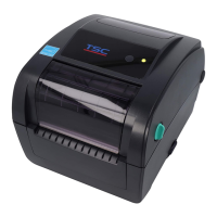
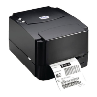
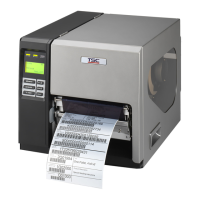
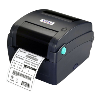
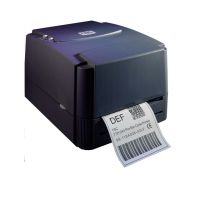
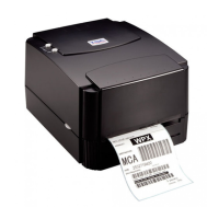
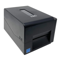
Overview of TSC Bar Code Printers

Front View of Printer Components

Illustrates the front view of the TC210 and TC200 series printers with labeled components.

Interior View of Printer

Details the internal components of the printer, showing labeled parts like print head, sensors, and rollers.

Rear View of Printer Interfaces

Presents the rear view of TC210 and TC200 series printers, highlighting interface ports and power switch.

Electronics and Board Connectors

Summary of Main Board Connectors

Lists and describes the connectors on the main board of the TC200/TC300 series printers.

Interface Pin Configurations

Details the pin configurations for RS-232C, USB, and Centronics interfaces.

Printer Mechanism Service Procedures

Replacing the LED or LCD Module

Provides step-by-step instructions for replacing the LED or LCD module, including screw removal.

Replacing the Main Board

Guides on how to remove and replace the main board of the printer, involving lower cover and connector disconnection.

Replacing the Head Open Sensor

Instructs on replacing the head open sensor, referencing lower cover removal and screw disconnection.

Replacing the Platen Roller Assembly

Details the procedure to remove and replace the platen roller assembly, involving top cover and platen holder tabs.

Replacing the Print Head Assembly

Explains how to replace the print head assembly, including removing bracket, spring plate, and harness.

Replacing the Stepping Motor

Provides steps for replacing the stepping motor, including lower cover removal, connector disconnection, and screw removal.

Replacing the Black-mark Sensor Module

Details the process of replacing the black-mark sensor module, involving main board removal and screw disconnection.

Replacing the Gap Sensor (Transmitter)

Guides on replacing the gap sensor (transmitter), involving main board removal and screw disconnection.

Replacing the Media Holder

Explains how to replace the media holder assembly, involving screw removal and spring assembly.

Peel-off Module Installation (Optional)

Provides instructions for installing the optional peel-off module, including platen holder tab manipulation and harness connection.

Cutter Module Installation (Optional)

Details the installation process for the optional cutter module, including harness threading and connection to the main board.

Troubleshooting Common Printer Issues

Printer Maintenance Procedures

Update History of Service Manual

Related product manuals