EasyManuals Logo

TSC TDP-247 User Manual

TSC TDP-247
47 pages
To Next Page IconTo Next Page
To Previous Page IconTo Previous Page
Page #19 background imageLoading...
Page #19 background image
16
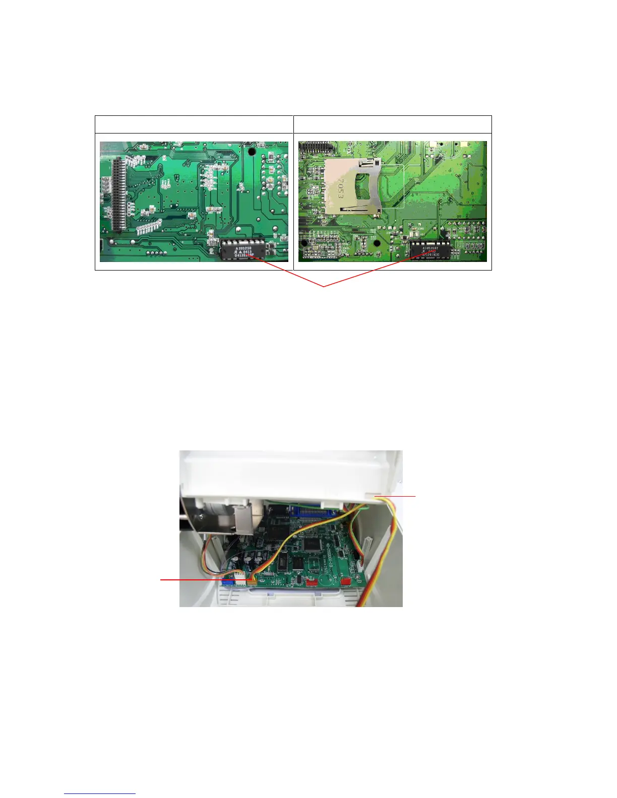
7. Plug in the Cutter Driver IC at U14(TDP-245) / U30(TDP-245
Plus/TDP-247/TDP-345) socket on the main board.
TDP-245 Model
TDP-245 Plus/TDP-247/TDP-345 Model
Note:
For Non-RoHS PCB, use cutter driver IC A3952SB
For RoHS PCB, use cutter driver IC A3953SB
8. Hold the lower cover and lift up the lower inner cover.
9. Arrange the cutter module harness through the bezel.
10. Connect the cutter module harness to the 4-pin socket on printer PCB.
11. Reassemble lower inner cover back to the lower cover.
12. Install the cutter module into the niche of the printer.
Bezel
Socket
Cutter Driver IC

Other manuals for TSC TDP-247

Questions and Answers:

Question and Answer IconNeed help?

Do you have a question about the TSC TDP-247 and is the answer not in the manual?

TSC TDP-247 Specifications

General IconGeneral
Print MethodThermal Transfer / Direct Thermal
Communication InterfaceUSB 2.0, RS-232
Power Supply100-240V AC, 50/60 Hz
Operating Temperature41°F - 104°F (5°C - 40°C)
Operating Humidity85% non-condensing
Max. Print Width4.09" (104 mm)
Label Width1.18" - 4.33" (30 mm - 110 mm)
Storage Temperature-40 ~ 60°C (-40 ~ 140°F)

Related product manuals