7-6 Model 3775 Condensation Particle Counter
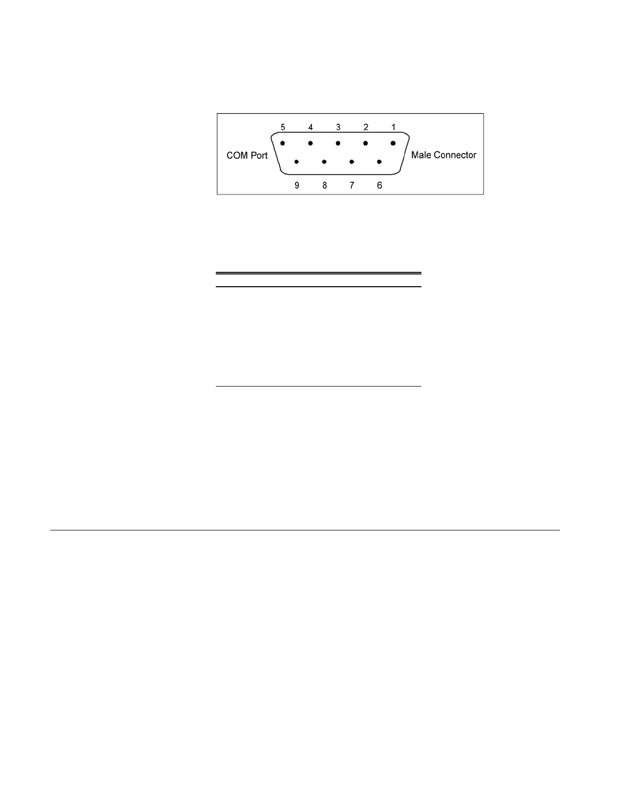
Note: This pin configuration is compatible with the standard IBM PC
serial cables.
Figure 7-5
RS-232 Connector Pin Designations
Table 7-1
Signal Connections for RS-232 Configurations
Pin Number RS-232 Signal
1 GND
2 Transmit Output
3 Receive Input
4 (Reserved)
5 GND
6 —
7 —
8 —
9 —
An external computer is connected to Serial 1 for basic instrument
communications and when Aerosol Instrument Manager software is
used. Serial 2 is used for attaching another instrument. Read and
write commands are sent and received from Serial 2 by the
computer connected to Serial 1. Serial 1 and Serial 2 can have
different baud rates and communications protocols. Normally, only
Serial 1 is used.
Commands
All commands and responses, unless specified as binary-encoded,
are sent or received as ASCII characters. All messages are
terminated with a <CR> (0x0D) character. All linefeeds (0x0A)
characters are ignored and none are transmitted. Commands are
case insensitive. Backspace character (0x08) will delete previous
characters in buffer.
In this specification, values enclosed by “<>” indicate ASCII
characters/values sent/received. For example, <,> indicates the
comma was sent or received via the communications channel.
Integers are 32-bit values. Floating point are IEEE() 32-bit values.