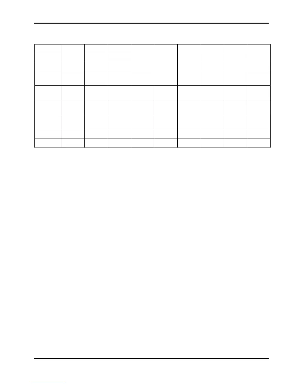
Jumpers are fitted to SEL1 to 7 to inform the microcontroller of the model type and to LK1 and
LK2 to power the opto-couplers, see table below.
SEL1 SEL2 SEL3 SEL4 SEL5 SEL6 SEL7 LK1 LK2
QL355
Yes
QL355P
Yes
QL355T
output 1
Yes Yes
QL355T
output 2
Yes
QL355TP
output 1
QL355TP
output 2
Yes
QL564
Yes
QL564P
Yes
The transformer windings are in series for the high voltage range and in parallel for the low
voltage range. D4, R14,C16 and D7,R15,C17 ensure the correct switching sequence of the range
relays.
IC8C and IC8D form an oscillator to drive the buzzer.
TP2 carries a synchronising pulse output which makes it possible to view the DAC sample and
hold outputs and the ADC input selector signals.
TP3 provides an output that toggles at each stage of the range change switching sequence.
Control Pcb
IC2 is a 16-bit DAC and the reference to it is supplied via IC19B which allows fine adjustment for
voltage and current settings. The DAC output is multiplexed into 7 sample and holds. IC14A is for
the voltage control (VC); when the output is off IC42B grounds its input via VR2. IC28B drives the
guard track (GV) round the VC sample and hold. An identical circuit is used for the current control
(IC). IC20B is the voltage control error amplifier and IC21A is a differential amplifier. With the
output at 35.0V VM will be -1.74V and VC will be 1.47V. Comparator IC26B is for over voltage
protection (OVP). A relay selects local or remote voltage sensing; if the voltage between an
output and its sense reaches 2xVbe either Q19 or Q20 will turn on turning the output off.
IC20A is the current control error amplifier and IC22 is a differential amplifier with a gain of 10.
R50 is used for the high current range and R51 is used for the 500mA range selected by IC23.
Q3 shorts out R51 when the high current range is selected. If the current limit is set to 2.0A IC will
be approximately 846mV. With a 2Amp load on the high range IM will be –1V. Over current
protection (OCP) is realised in software. When the power supply is in constant current mode
IC20A has control and comparator IC17B drives the CI line high.
IC37 is a 12-bit ADC; ADREF is adjusted for voltage and current measurements and is
approximately 4V. IC27B has a gain of –2; therefore if, for example, VM was –2V then the output
of IC27B would be +4V. Offsets are trimmed by ADOFST. To achieve 13-bit resolution two
measurements are taken with and without the 13
th
bit subtracted from the input selected by
IC24C.
Any trip condition is latched by IC29 and IC30 and cleared by the microcontroller by pressing
escape. IC18 is used for synchronising the switching of the outputs on triple units.
9