Calibration
Refer to the General section for dismantling instructions and safety precautions. Normal
calibration is done without opening the instrument.
Allow 10 minute warm-up before commencing calibration.
Refer to the User Manual for detailed operation of these power supplies.
Equipment Required
A 5.5 digit multimeter with better than 0.02% accuracy on dc volts and better than 0.12%
accuracy on dc current (to 5A); alternatively use a precision shunt for current measurement.
Calibration
To enter calibration press
shift
#, 99. If the instrument is a long way out of calibration or has
been repaired, the default calibration values should be loaded first by pressing shift
#, 91.
Pressing Escape at anytime will abort the calibration procedure and revert to the stored
calibration values.
Having entered calibration mode, follow the table below. To increment to the next step press OK.
The calibration must be done in sequence. At the end of calibration press OK to store the
calibration. The instrument automatically sets the range and settings at each step.
Use the spin-wheel to adjust calibration; holding down the
Jog Off
key will give x100
increments to speed up calibration. Pressing shift
will show the calibration value.
On triple units (QL355T and QL355TP) calibrate both output 1 and output 2.
There are two internal adjustments which are factory set and will normally only require adjustment
if a component has been changed in the associated area. If this is so proceed as follows. VR1
and VR2 are both located near the top of the control pcb. They are accessible from both sides of
the board. Turn them both fully clockwise as viewed from the component side, fully anti-clockwise
as viewed from the solderside. Adjustment is done with the output set to off. Connect an ammeter
across the output terminals and adjust VR1 for +1mA. Remove ammeter and connect voltmeter
and adjust for VR2 –10mV. (minus or negative 10mV).
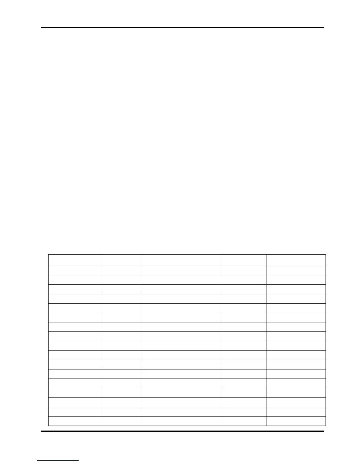
QL355
Step/Range Settings Adjust for:- Load Detail
1, 35V 3A 0.01V 3A 10mV ± 0.5mV DVM o/p 0V
2, 35V 3A 0.01V 3A 0.010V on display DVM V readback zero
3, 35V 3A 35V 3A 35V ± 0.5mV DVM o/p V span
4, 35V 3A 35V 3A 35.000 on display DVM V readback span
5, 35V 3A 0.01V 3A 10mV ± 0.5mV DVM o/p 0V
6, 35V 3A 35V 3A 35V ± 0.5mV DVM o/p V span
7, 35V 3A 2V 0.001A 1mA ± 0.5mA milli-ammeter o/p A offset
8, 35V 3A 2V 0.001A 0.001 on display milli-ammeter A readback zero
9, 35V 500mA 2V 0.1mA 0.1mA ± 0.05mA milli-ammeter o/p mA offset
10, 35V 500mA 2V 0.1mA flashing 0.0/0.1 on display milli-ammeter mA readback zero
change load
11, 15V 5A 2V 4A 4A ± 0.5mA ammeter o/p A span
12, 15V 5A 2V 4A 4.000 on display ammeter A readback span
13, 15V 5A 2V 4.1A 4.100 on display ammeter A readback 13bit
14, 35V 500mA 2V 400mA 400mA ± 0.05mA ammeter o/p mA span
15, 35V 500mA 2V 400mA 400.0 on display ammeter mA readback span
16, 35V 500mA 2V 410mA 410.0 on display ammeter mA readback 13bit
11