Circuit Descriptions
The Power board contains the main power supply and the auxiliary supplies used internally, the
output series regulator transistors, the microcontroller, display drivers and some control logic.
The Control board contains voltage and current control, ADC and DAC and some control logic.
The linear regulator is in series with the positive output but, because of the way in which the
control circuit is referenced to the +ve output, it is convenient to consider the regulated output as
the negative side.
To help reading the circuit diagrams the two connectors between the power and control pcbs join
as follows. PJ14 to PJ18 and PJ20 to PJ19.
Power Pcb
The main windings are connected either in series (for the high voltage range) or in parallel (for
the low voltage range) by the range relays and an electronic tap change at approximately half
range is used to reduce dissipation. Bridge rectifier BR1 feeds C4 the reservoir capacitor when
tap change is low. When tap change is high, two of the diodes in BR1 are bypassed by SCR1 and
SCR2. Voltages are listed below at nominal mains (230V).
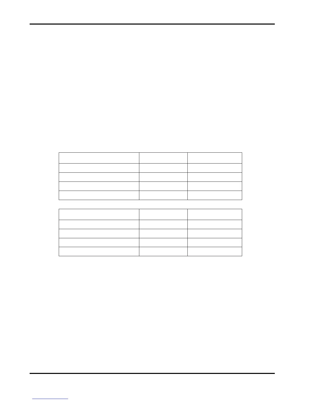
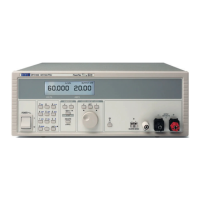
QL355
35V/3A 15V/5A
Secondary – high tap, no-load 39.8VAC 19.9VAC
Secondary – high tap, full-load 37VAC 18.9VAC
C4 – high tap, no-load 51.5VDC 24.5VDC
C4 – high tap, full-load 44.7VDC 21.9VDC
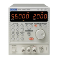
QL564
56V/2A 25V/4A
Secondary – high tap, no-load 60VAC 30.1VAC
Secondary – high tap, full-load 56VAC 28.6VAC
C4 – high tap, no-load 79.5VDC 38.4VDC
C4 – high tap, full-load 69.5VDC 35.2VDC
A 30Vrms centre tapped winding and full wave rectification provide the auxiliary supplies. IC1
generates +10V and IC2 –5V. A 10.4Vrms winding and full wave rectification power the relays
and fan and IC3 provides the +5V for the microcontroller, display and control logic.
Comparator IC6A provides the system reset signal and comparator IC6B provides the power fail
signal to the microcontroller to store the instrument settings at power down.
The fan speed is regulated by a pulse width modulator in the microcontroller; if the heatsink
exceeds a certain temperature measured by Q22, comparator IC50A switches the fan to full
speed. If the heatsink temperature continues to rise IC50B will pull the over-temperature line low
which will turn the output off.
Q15 and Q16 are the series regulator transistors; long-tailed pair Q17 and Q21 ensure current
sharing. The +10V supply to emitter follower Q14 is via switch Q13 which is turned on after a
delay to prevent output glitches when power is turned on.
Microcontroller IC39, which is factory programmed, writes the calibration values and instrument
settings to non-volatile memory IC31, reads the keyboard, spin-wheel and status of the
instrument via shift registers (4021s), reads the ADC, outputs data via shift registers (4094s) and
display drivers IC32, IC33 and IC38, and writes to the DAC.
8