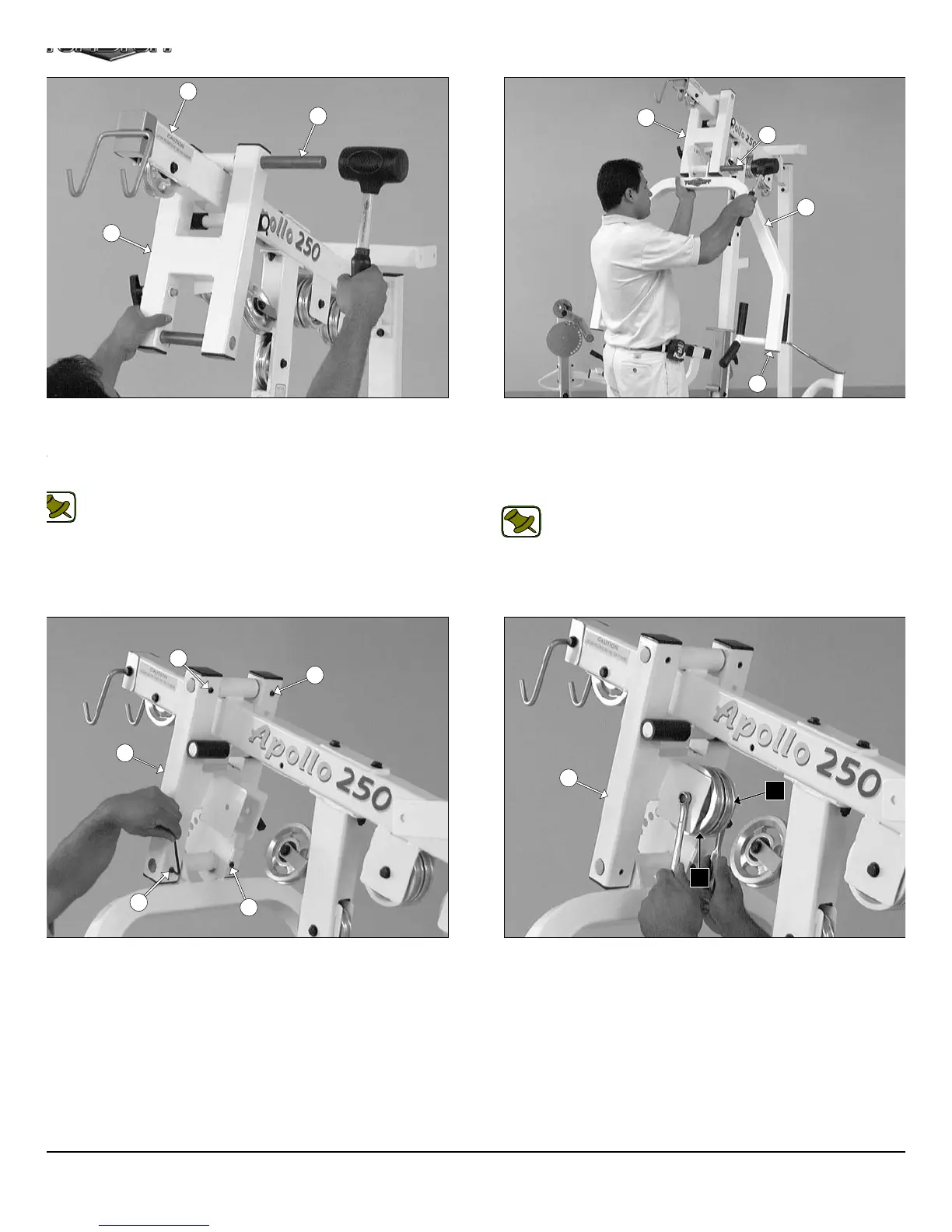
IG. 28 Using a rubber mallet, insert one Pivot Axle 1 X 8 1/8 (#18)
rough the holes of the Press Bar Selector Housing (#17) and
rough the receptacle of the Top Pulley Housing (#5) until the Pivot
xle 1 X 8 1/8 (#18) is flush with both sides of the Press Bar Selector
ousing (#17).
Note: It is recommended to grease the Pivot Axles 1 X 8 1/8
(#18) with multi-purpose grease prior to assembling.
IG. 30 Secure the two Pivot Axles 1 X 8 1/8 (#18) to the Press
ar Selector Housing (#17) using four Set Screws 3/8-16 X 1/2 (#69).
se the Supplied Hex Key 3/16 (#126) for securing these Set Screws
8-16 X 1/2 (#69) into the threaded sockets on the Press Bar Selector
ousing (#17). Next, clean the ends of the Pivot Axles 1 X 8 1/8
18) and apply four 1” Rd. Silver Mylar Decals (#131–Not shown).
hese decals are used to hide and protect the ends of the axles.
FIG. 29 Using a rubber mallet, insert two Plastic Insert Caps 2” S
(#86) into the tube-ends of the Press Bar (#1). Next, insert the Pres
Bar (#1) up into the Press Bar Selector Housing (#17) and support i
into place using the push-pull pin 1/2 X 3 1/2 (#73). Next, using
rubber mallet, insert the Pivot Axle 1 X 8 1/8 (#18) into the Press B
Selector Housing (#17) and through the Press Bar (#1).
Note: Refer to Fig. 83 on page 30 for further clarification of th
assembly.
FIG. 31 Next, attach two Pulleys 4 1/2 Rd. (#68-Labeled C3, C5) t
the Press Bar Selector Housing (#17) using one Hex Head C
Screw 3/8-16 X 2 3/4 (#107), two Flat Washers SAE 3/8” (#91), an
one Nylon Insert Jam Lock Nut 3/8-16 (#101).
9
18
5
17
1
18
17
17
69
69
69
69
17
C3
C5
85
AP-250S_AP-250D Apollo 2-Stack Gym Syste