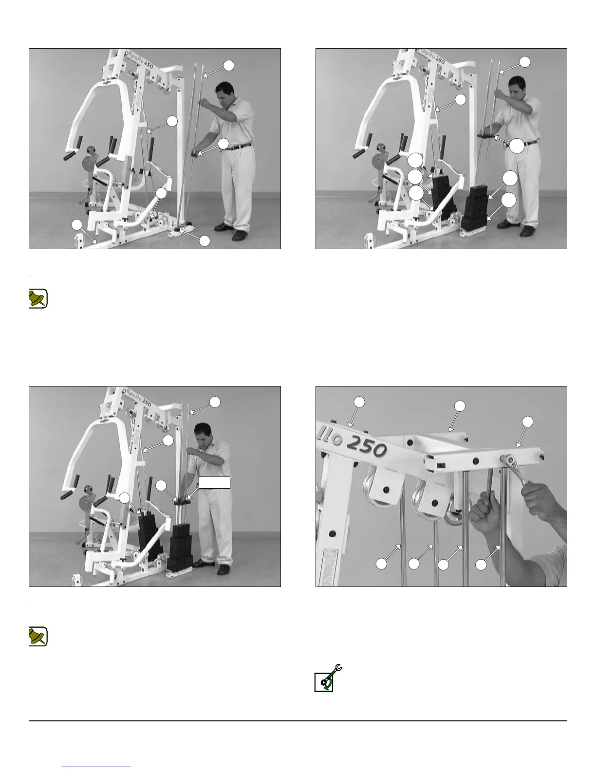
IG. 32 Insert the four Guide Rods 3/4 X 72 (#21) into the
ceptacles of the Base Frame (#2), as shown above. Next, insert four
ubber Donuts 3/4 X 2 1/2 (#81) onto the Guide Rod 3/4 X 72 (#21).
Note: Lubricate the Guide Rods 3/4 X 72 (#21) with a silcone or
teflon lubricant at this time.
IG. 34 Slide the Top Plate/Selector Bar (#24) over the Guide
ods (#21) allowing it to come to rest on top of the completed weight
ack. Same process for both weight stacks.
Note: Be sure the Label located on the Top Plate/Selector Bar
(#24) is facing out, as shown above, before sliding the Top
Plate/Selector Bar (#24) onto the Guide Rods (#21).
FIG. 33 Carefully begin sliding the Weight Plates over the Guid
Rods (#21) beginning with the five 15 Lb. Weight Plates (#134) at th
bottom, the nine 10 Lb. Weight Plates (#23) in the middle, and the fi
5 Lb. Weight Plates (#133) on top of the weight stack. Same proce
for both weight stacks.
FIG. 35 Maneuver the two Guide Rods (#21) into the holes on th
bottom side of the Guide Rod Retainer Housing (#20). Next, secu
the Guide Rod Retainer Housing (#20) along with the two capti
Guide Rods (#21) to the Top Pulley Assembly (#5) using two H
Head Cap Screws 3/8-16 X 2 3/4 (#107), four Flat Washers SA
3/8” (#91), and two Nylon Insert Jam Lock Nuts 3/8-16 (#101). Repe
the same procedure for the other Guide Rod Retainer Housing (#20)
Loosely Fasten: Do not completely fasten this hardwa
assembly at this time, as it will be completely fastened later
the assembly process.
10
wner
s
anua
:
ssem
y
nstruct
on
21
81
81
21
81
2
21
21
134
133
133
134
21
21
24
24
LABEL
5
20
20
21
2121
21
23
23
P-250S_AP-250D Apollo 2-Stack Gym System