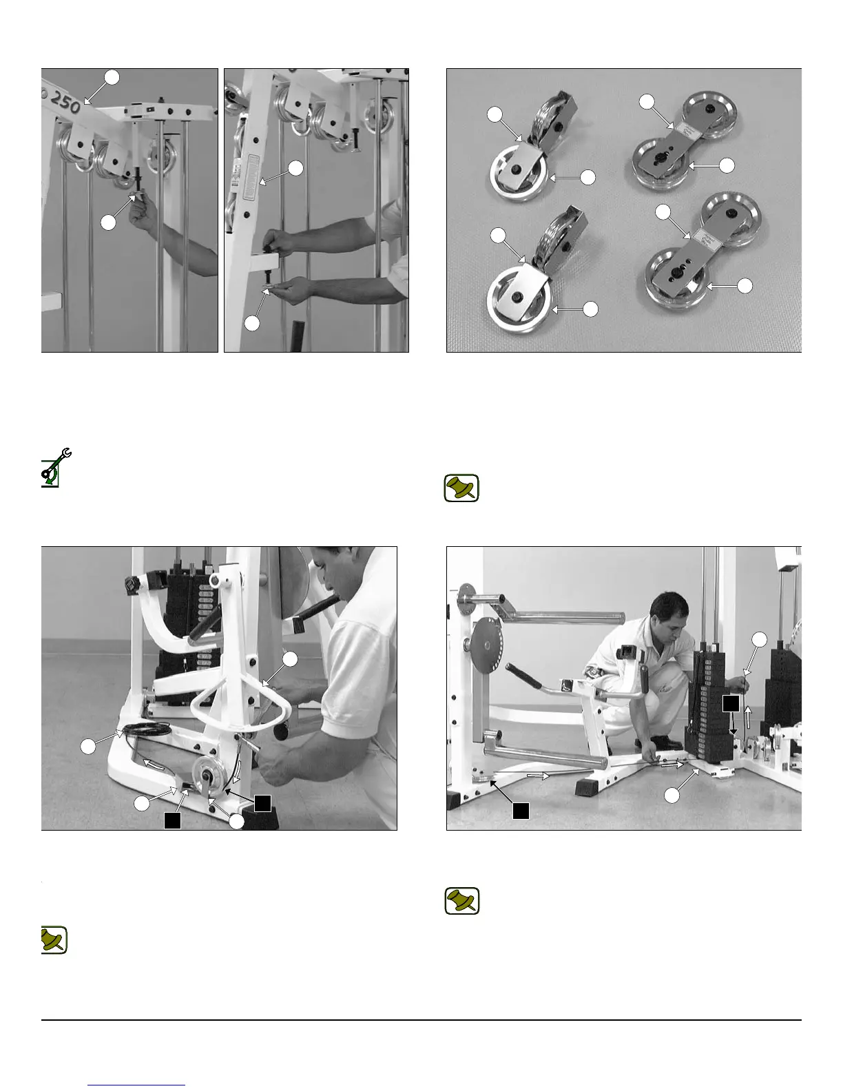
IG. 42 Attach the looped-end of the Leg Extension Cable (#41) to
e bracket of the Actuator Arm (#43) using one Hex Head Cap Screw
8-16 X 1 (#113), and one Nylon Insert Jam Lock Nut 3/8-16 (#101).
oute the Leg Extension Cable (#41) under the Pulley 4 1/2 Rd. (#68-
beled A1), then route between the Pulley 4 1/2 Rd. (#68-Labeled A2)
d the Pulley Cover Plate (#50).
Note: Refer to the Cable Mapping Diagram on page 24 for
further detailed illustration of the Leg Extension Cable (#41)
routing.
FIG. 41 Locate the two Closed-End Double Pulley Brackets (#2
and attach four Pulleys 4 1/2 Rd. (#68) using four Hex Head Ca
Screws 3/8-16 X 1 3/4 (#110), eight Flat Washers SAE 3/8” (#91), an
four Nylon Insert Jam Lock Nuts 3/8-16 (#101). Next, locate the fo
Adjustable Double Pulley Plates (#27) and attach four Pulleys 4 1/
Rd. (#68) using four Hex Head Cap Screws 3/8-16 X 1 3/4 (#110), eig
Flat Washers SAE 3/8” (#91), and four Nylon Insert Jam Lock Nuts 3/
16 (#101).
Note: The four holes on the Adjustable Double Pulley Plat
(#27) are used to adjust the cable tension once the cable routin
has been completed.
FIG. 43 Next, continue to route the Leg Extension Cable (#4
under the Nylon Pulley 4 1/2 Rd. (#68-Labeled A3) located on the Bas
Frame (#2).
Note: Refer to the Cable Mapping Diagram on page 24 f
further detailed illustration of the Leg Extension Cable (#4
routing.
IG. 40 Next, thread one Adjustable Stopper (#33) into the threaded
cket located on the Top Pulley Housing (#5), as shown in the left
cture above. Next, insert the other Adjustable Stopper (#33) into the
ceptacle located on the Front Upright (#3) and secure it into place
ing one Flat Washer SAE 1/2” (#90), and one Regular Hex Nut 1/2-13
99).
Loosely Fasten: Do not completely fasten this hardware
assembly at this time, as it will be completely fastened later in the
assembly process.
12
wner
s
anua
:
ssem
y
nstruct
on
5
33
33
3
27
27
26
26
68
68
68
68
43
A1
50
28
A2
41
41
A2
2
A3
P-250S_AP-250D Apollo 2-Stack Gym System