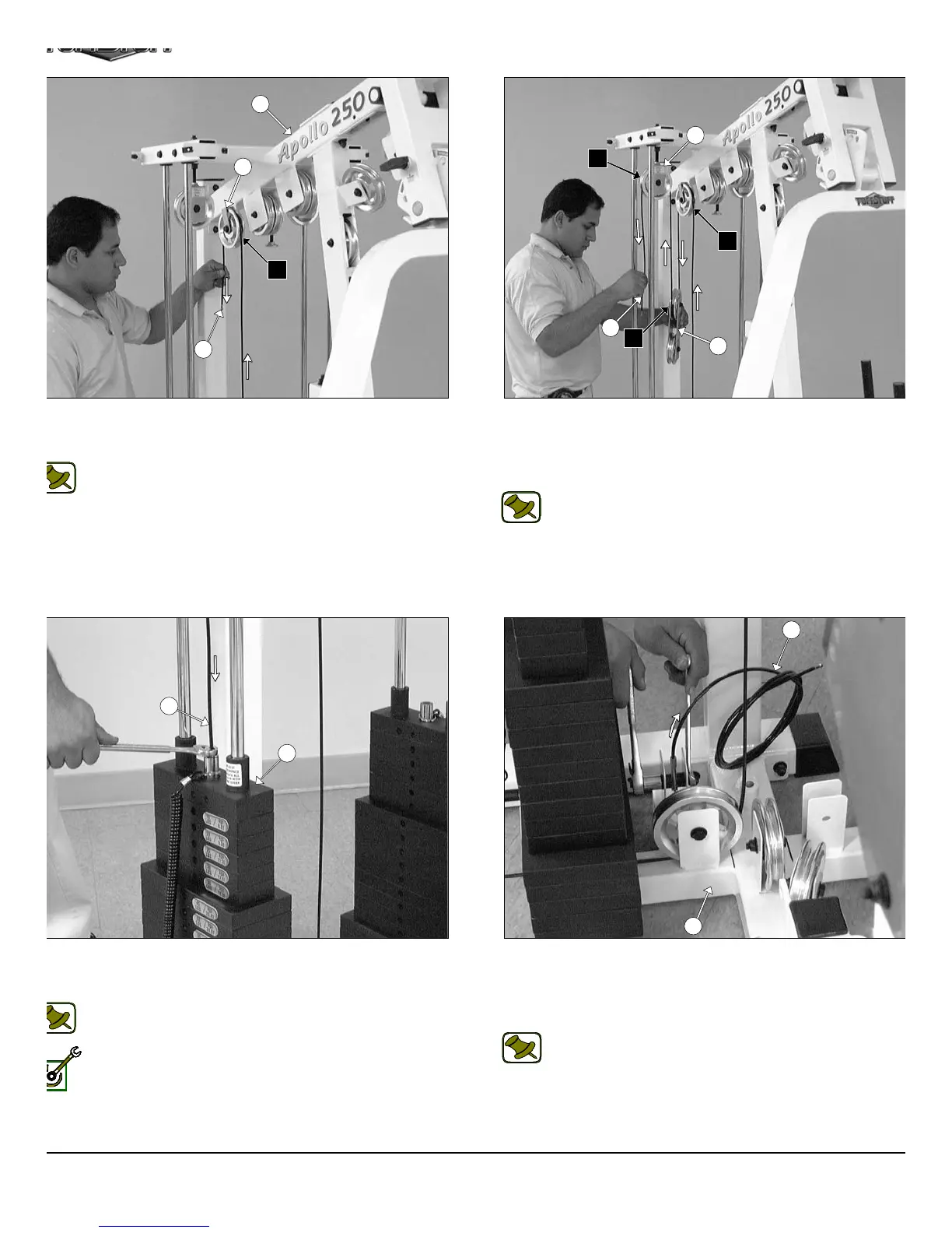
IG. 44 Route the Leg Extension Cable (#41) up and over the
ulley 4 1/2 Rd. (#68-Labeled A4) located on the Top Pulley Housing
5).
Note: Refer to the Cable Mapping Diagram on page 24 for
further detailed illustration of the Leg Extension Cable (#41)
routing.
IG. 46 Next, attach the Leg Extension Cable (#41) to the Top
late/ Selector Bar (#24) using one Split Bolt 1/2-13 X 1 (#94) and one
plit Lock Washer 1/2” (#93).
Note: Refer to Fig. A on page 24 for further clarification of this
hardware assembly.
Fully Fasten: Proceed to fully fasten this hardware assembly.
FIG. 45 Next, locate the assembled Adjustable Double Pulle
Plates (#27) and route the Leg Extension Cable (#41) down an
under the Pulley 4 1/2 Rd. (#68-Labeled A5). Next, continue to rou
the Leg Extension Cable (#41) up and over the Nylon Pulley 4 1/2 R
(#68-Labeled A6).
Note: Refer to the Cable Mapping Diagram on page 24 f
further detailed illustration of the Leg Extension Cable (#4
routing.
FIG. 47 Attach the looped end of the Leg Extension Tension Cabl
(#42) to the pulley bracket of the Base Frame (#2) using one Hex He
Cap Screw 3/8-16 X 1 3/4 (#110), two Flat Washers SAE 3/8” (#91
two Nylon Spacers 3/8 X 3/8 (#120), and one Nylon Insert Jam Lo
Nut 3/8-16 (#101).
Note: Refer to Fig. A on page 25 for further clarification of th
hardware assembly.
13
5
41
A4
28
36
A4
A5
A6
27
41
24
41
2
42
AP-250S_AP-250D Apollo 2-Stack Gym Syste