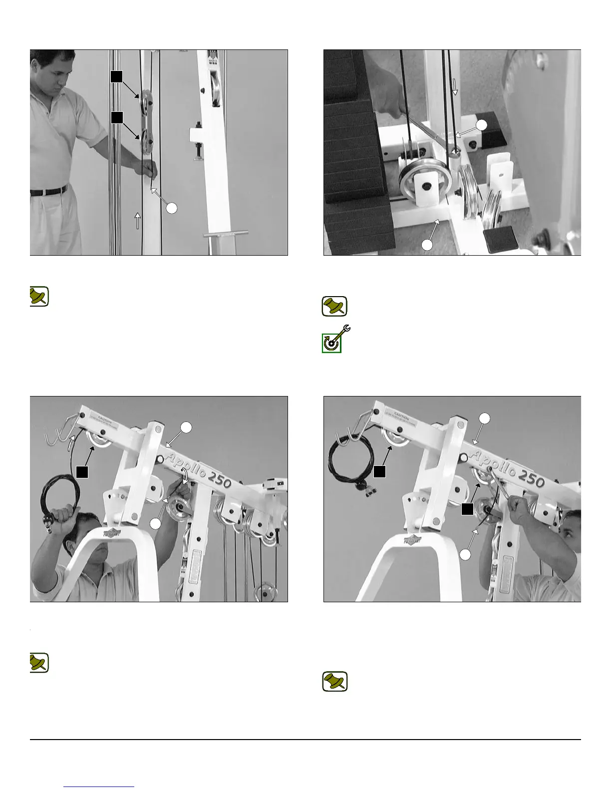
IG. 48 Next, continue to route the Leg Extension Tension Cable
42) up and over the Pulley 4 1/2 Rd. (#68-Labeled B1).
Note: Refer to the Cable Mapping Diagram on page 25 for
further detailed illustration of the Leg Extension Tension Cable
(#42) routing.
IG. 50 Begin routing the Lat Cable (#37) up and over the Pulley 4
2 Rd. (#68-Labeled C1) and into the tube of the Top Pulley
ssembly (#5). Then, pull the Lat Cable (#37) down through the
ening at the bottom of the Top Pulley Assembly (#5).
Note: Refer to the Cable Mapping Diagram on page 26 for
further detailed illustration of the Lat Cable (#37) routing.
FIG. 49 Attach the end of the Leg Extension Tension Cable (#4
to the threaded socket of the Base Frame (#2) using one Split Bolt 1/
13 X 1 (#94), and one Split Lock Washer 1/2” (#93).
Note: Refer to Fig. B on page 25 for further clarification of thi
hardware assembly.
Fully Fasten: Proceed to fully fasten this hardware assembly.
FIG. 51 Insert a Pulley 4 1/2 Rd. (#68-Labeled C2) into the slot
the bottom of the Top Pulley assembly (#5) and secure it into plac
using one Hex Head Cap Screw 3/8-16 X 2 1/2 (#108), two Fl
Washers SAE 3/8” (#91), and one Nylon Insert Jam Lock Nut 3/8-1
(#101). Be sure the cable is routed properly into the groove of the Pu
ley 4 1/2 Rd. (#68-Labeled C2).
Note: Refer to the Cable Mapping Diagram on page 26 f
further detailed illustration of the Lat Cable (#37) routing.
14
wner
s
anua
:
ssem
y
nstruct
on
42
B1
A5
2
42
5
37
C1
5
C1
C2
37
P-250S_AP-250D Apollo 2-Stack Gym System