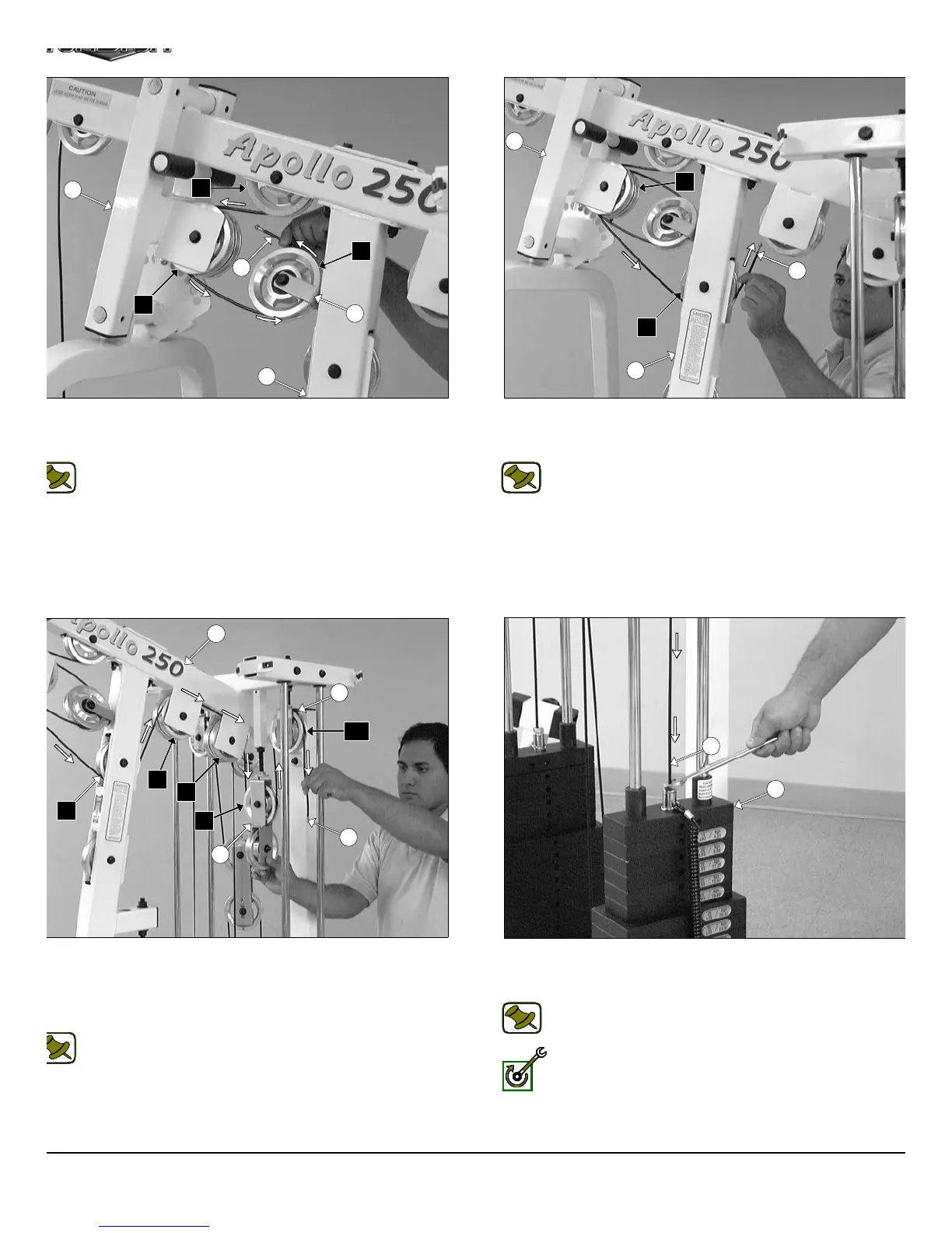
IG. 52 Next, continue to route the Lat Cable (#37) around the
ulley 4 1/2 Rd. (#68-Labeled C3), then across and over the Pulley 4
2 Rd. (#68-Labeled C4).
Note: Refer to the Cable Mapping Diagram on page 26 for
further detailed illustration of the Lat Cable (#37) routing.
IG. 54 Route the Lat Cable (#37) over the Pulleys 4 1/2 Rd. (#68-
beled C7, C8). Next, locate one of the Closed-End Double Pulley
rackets (#26) and continue to route the Lat Cable (#37) down and
der the Pulley 4 1/2 Rd. (#68-Labeled C9), then up and over the
ulley 4 1/2 Rd. (#68-Labeled C10).
Note: Refer to the Cable Mapping Diagram on page 26 for
further detailed illustration of the Lat Cable (#37) routing.
FIG. 53 Next, continue to route the Lat Cable (#37) over the Pulley
1/2 Rd. (#68-Labeled C5), then through the Front Upright (#3) an
under the Pulley 4 1/2 Rd. (#68-Labeled C6).
Note: Refer to the Cable Mapping Diagram on page 26 f
further detailed illustration of the Lat Cable (#37) routing.
FIG. 55 Next, attach the Lat Cable (#37) to the Top Plate/ Select
Bar (#24) using one Split Bolt 1/2-13 X 1 (#94), and one Split Lo
Washer 1/2” (#93).
Note: Refer to Fig. B on page 26 for further clarification of thi
hardware assembly.
Fully Fasten: Proceed to fully fasten this hardware assembly.
15
28
C4
C2
37
C3
17
3
17
C5
3
37
C6
5
C6
C7
36
C10
C8
C9
37
27
37
24
AP-250S_AP-250D Apollo 2-Stack Gym Syste