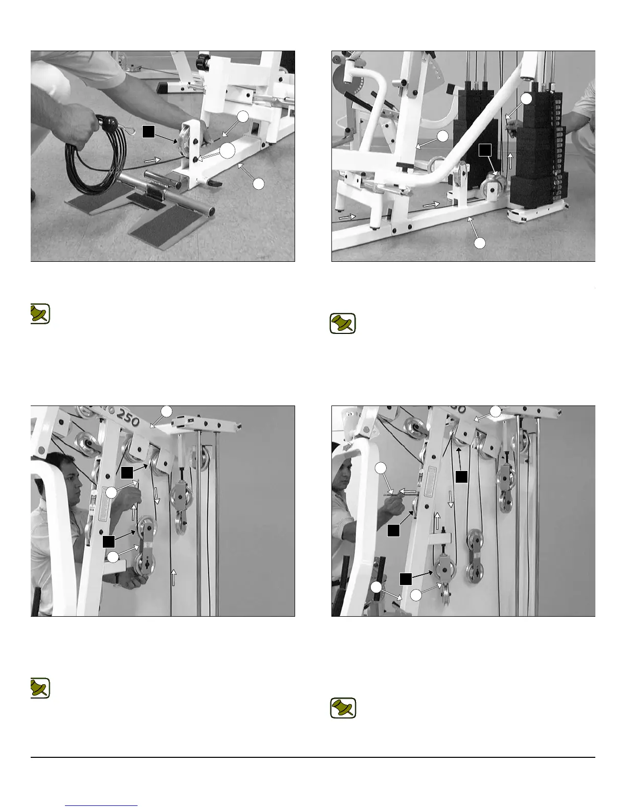
IG. 56 Next, begin routing the Low Row/Abdominal Cable (#38)
tween the Pulley 4 1/2 Rd. (#68–Labeled D1) and the Hex Head Cap
crew 3/8-16 X 2 (#109) as shown above.
Note: Refer to the Cable Mapping Diagram on page 27 for
further detailed illustration of the Low Row/Abdominal Cable
(#38) routing
IG. 58 Continue to route the the Low Row/Abdominal Cable (#38)
and over the Pulley 4 1/2 Rd. (#68-Labeled D3) located on the Top
ulley Assembly (#5). Next, locate one of the assembled Adjustable
ouble Pulley Plates (#27) and route the Low Row/ Abdominal Ca-
le (#38) down and under the Pulley 4 1/2 Rd. (#68-Labeled D4).
Note: Refer to the Cable Mapping Diagram on page 27 for
further detailed illustration of the Low Row/Abdominal Cable
(#38) routing.
FIG. 57 Continue to route the Low Row/Abdominal Cable (#3
through the slots of the Front Upright (#3) and the Base Frame (#2
Next, route the Low Row/Abdominal Cable (#38) under the Pulley
1/2 Rd. (#68-Labeled D2).
Note: Refer to the Cable Mapping Diagram on page 27 f
further detailed illustration of the Low Row/Abdominal Cab
(#38) routing.
FIG. 59 Route the the Low Row/Abdominal Cable (#38) up an
over the Pulley 4 1/2 Rd. (#68-Labeled D5). Next, locate the other a
sembled Closed-End Double Pulley Bracket (#26) and route the Lo
Row/Abdominal Cable (#38) down and under the Pulley 4 1/2 R
(#68-Labeled D6). Continue to route the the Low Row/Abdominal C
ble (#38) through the opening of the Front Upright (#3), then up an
over the Pulley 4 1/2 Rd. (#68-Labeled D7).
Note: Refer to the Cable Mapping Diagram on page 27 f
further detailed illustration of the Low Row/Abdominal Cab
(#38) routing.
16
wner
s
anua
:
ssem
y
nstruct
on
2
38
D1
3
2
38
2
D2
27
D4
38
D3
5
26
D6
D7
38
D5
3
5
109
P-250S_AP-250D Apollo 2-Stack Gym System