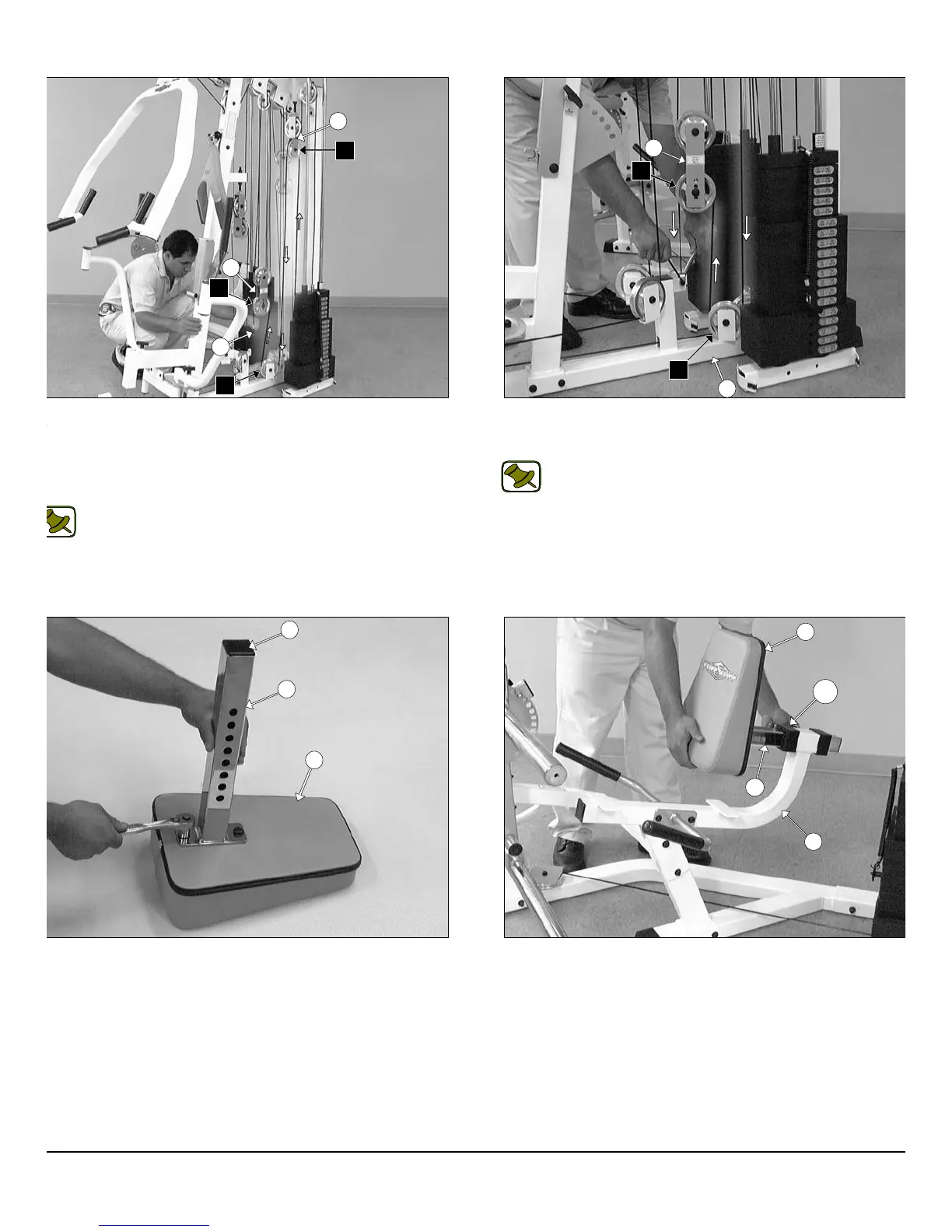
IG. 64 Route the Tension Cable (#40) up and over the Pulley 4 1/2
d. (#68-Labeled F1) on the Closed-End Pulley Bracket (#26). Next,
ute the cable down and under the Pulley 4 1/2 Rd. (#68-Labeled F2)
cated on the Base Frame (#2), then up and over the Pulley 4 1/2 Rd.
68-Labeled F3) located on the assembled Double Pulley Plates
27).
Note: Refer to the Cable Mapping Diagram on page 29 for
further detailed illustration of the Tension Cable (#40) routing..
IG. 66 Using a rubber mallet, insert one Plastic Insert Cap 2” Sq.
86) into the tube-end of the Back Pad Adjustable Tube (#47). Next,
tach the Back Pad Adjustable Tube (#47) to the Leg Extension
ack Pad (#49) using two Hex Head Cap Screws 3/8-16 X 1 1/4
112), and two Flat Washers SAE 3/8” (#91).
FIG.65 Secure the end of the Tension Cable (#40) to the Bas
Frame (#2) using one Strap Bracket #20 (#118), one Shoulder Bolt 3
X 3/4 (#117), and one Nylon Insert Lock Nut 5/16-18 (#102).
Note: Refer to Fig. A on page 29 for further clarification of thi
hardware assembly.
FIG. 67 Insert the assembled Back Pad Adjustable Tube (#47)
the Leg Extension Seat Frame (#12).
18
wner
s
anua
:
ssem
y
nstruct
on
26
27
F1
F2
F3
40
2
27
F3
F2
49
47
86
47
12
49
138
P-250S_AP-250D Apollo 2-Stack Gym System