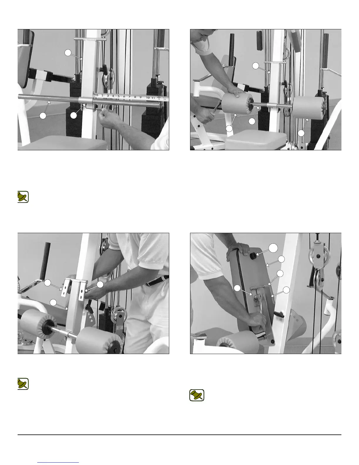
IG. 72 Next, insert the Foot Roll Tube 1 X 27 (#30) into the
ceptacle of the Adjustable Back Pad Bracket (#10). Use a measur-
g tape to center the Foot Roll Tube 1 X 27 (#30) with the Adjustable
ack Pad Bracket (#10). Next, secure the Foot Roll Tube 1 X 27
30) to the Adjustable Back Pad Bracket (#10) using one Set Screw
4-20 X 1/4 (#70).
Note: Refer to Fig. 85 on page 30 for further clarification of this
hardware assembly.
IG. 74 Attach two Metal Hinges (#67) to the axle of the Adjustable
ack Pad Bracket (#10). Be sure to position the Metal Hinges (#67)
shown above.
Note: Refer to Fig. 84 on page 30 for further clarification of this
hardware assembly.
FIG. 73 Insert two Foam Rolls 1 X 5 1/2 X 7 1/4 (#52) to the tub
ends of the Foot Roll Tube 1 X 27 (#30) and secure them into pla
using two Hex Head Cap Screws 3/8-16 X 1 1/2 (#111).
FIG. 75 Attach a Rubber Bumper 3/8 X 1 1/2 (#132) to the Benc
Press Back Pad (#34) using one Hex Head Cap Screw 3/8-16 X 1 1/
(#111). Next, attach the Bench Press Back Pad (#34) to the Met
Hinges (#67) using two Hex Head Cap Screws 3/8-16 X 1 1/4 (#112
and two Flat Washers SAE 3/8” (#71).
Note: Refer to Fig. 84 on page 30 for further clarification of th
hardware assembly.
20
wner
s
anua
:
ssem
y
nstruct
on
10
30
70
30
52
52
10
10
67
67
34
67
67
10
132
P-250S_AP-250D Apollo 2-Stack Gym System