A1
A2
A4
A3
A6
A5
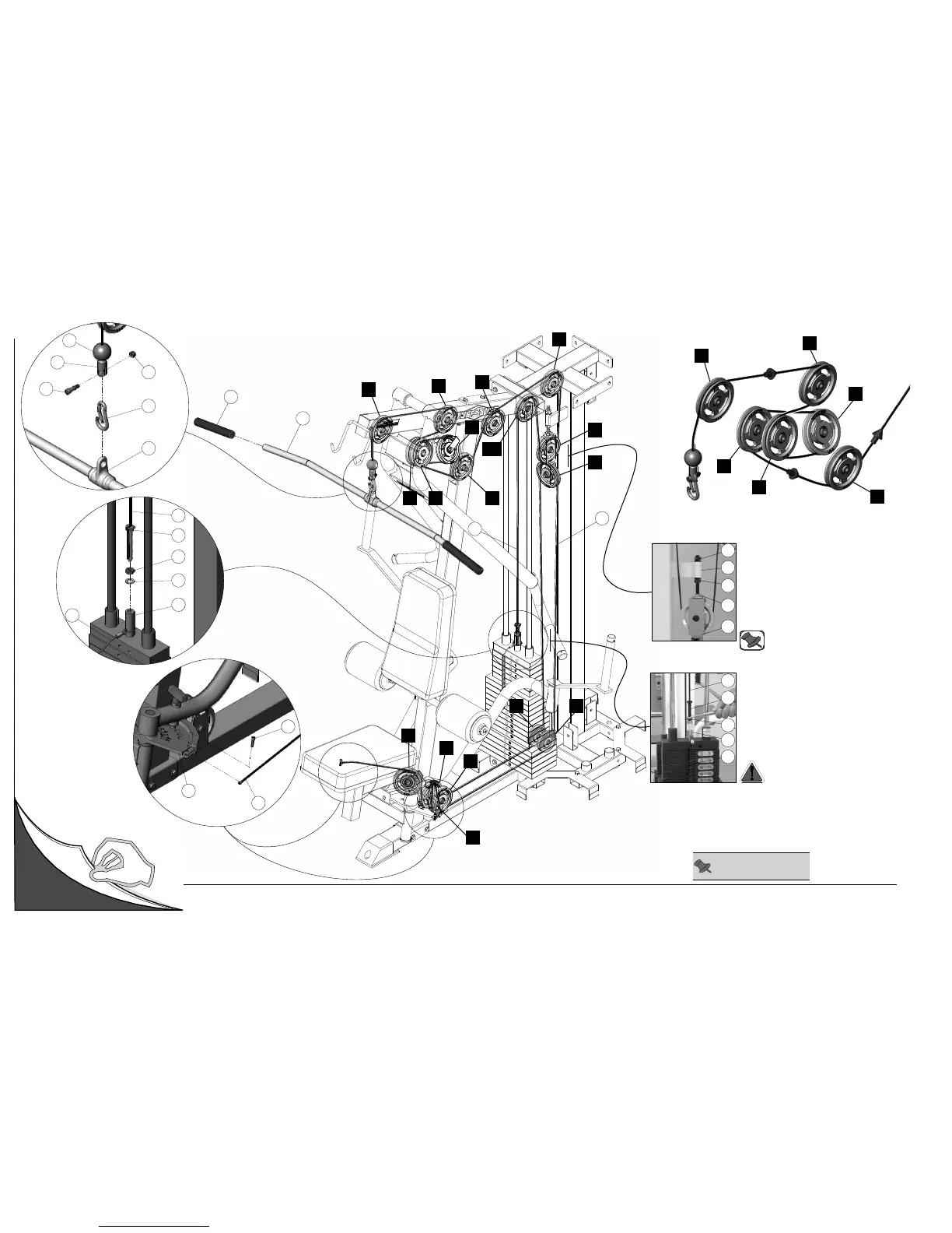
Cable Mapping Diagram Mid Row Station
Adjustable Stopper (#30)
1. Loosen both Finished Hex Nuts 1/2-13
(#88).
2. Twist the
Adjustable Stopper (#30) to
left or right until it makes contact with the
Closed-End Double Pulley Bracket (#12).
3. Re-tighten the Finished Hex Nuts 1/2-13
(#88) to complete the cable adjustment.
88
12
30
53
88
22
31
58
151
88
Cable Adjustment
1. Loosen the Finished Hex Nut 1/2-13 (#88).
2. Thread the Cable Hex Tap Bolt (#151) in
or out of the threaded socket of the Selector
Bar (#58) to give the Cables proper tension.
3. Re-tighten the Finished Hex Nut 1/2-13
(#88) to complete the adjustment.
Note: Be sure that the
Closed-End
Double Pulley Bracket (#12) is resting
on the Adjustable Stopper (#30).
Caution: Make sure the Cable Hex
Tap Bolt (#151) is threaded at least
1/2” into the threaded socket of the
Selector Bar (#58) once the cable
adjustment has been completed.
Unfold
Page
Note: Some parts have
been cut away for clarity.
FIG. C
22
151
88
153
58
31
146
37
60
139
111
24
25
A6
B2
B6
B7