10
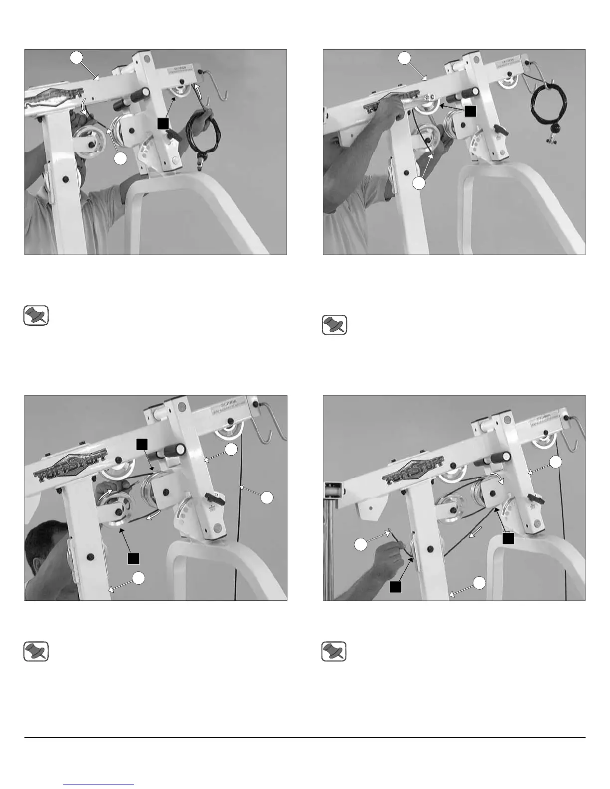
FIG. 29 Begin routing the Lat Cable (#22) up and over the Pulley 4
1/2 Rd. (#67-Labeled A1) and into the tube of the Top Pulley
Assembly (#49). Then, pull the Lat Cable (#22) down through the
opening at the bottom of the Top Pulley Assembly (#49).
Note: Refer to the Cable Mapping Diagram on fold-out page 21
for further detailed illustration of the Lat Cable (#22) routing.
FIG. 30 Insert a Pulley 4 1/2 Rd. (#67-Labeled A2) into the slot at
the bottom of the Top Pulley assembly (#49) and secure it into place
using one Hex Head Cap Screw 3/8-16 X 2 1/2 (#99), two Flat Washers
SAE 3/8” (#93), and one Nylon Insert Jam Lock Nut 3/8-16 (#118). Be
sure the cable is routed properly into the groove of the Pulley.
Note: Refer to the Cable Mapping Diagram on fold-out page 21
for further detailed illustration of the Lat Cable (#22) routing.
49
22
A1
22
A2
49
Assembly Instructions
FIG. 31 Next, continue to route the Lat Cable (#22) around the
Pulley 4 1/2 Rd. (#67-Labeled A3), then across and over the Pulley 4
1/2 Rd. (#67-Labeled A4).
Note: Refer to the Cable Mapping Diagram on fold-out page 21
for further detailed illustration of the Lat Cable (#22) routing.
FIG. 32 Next, continue to route the Lat Cable (#22) over the Pulley 4
1/2 Rd. (#67-Labeled A5), then through the Front Upright (#16) and
under the Pulley 4 1/2 Rd. (#67-Labeled A6).
Note: Refer to the Cable Mapping Diagram on fold-out page 21
for further detailed illustration of the Lat Cable (#22) routing.
16
A4
A3
41
22
16
22
A5
A6
41
Apollo Modular Gym System (Base Unit)