9
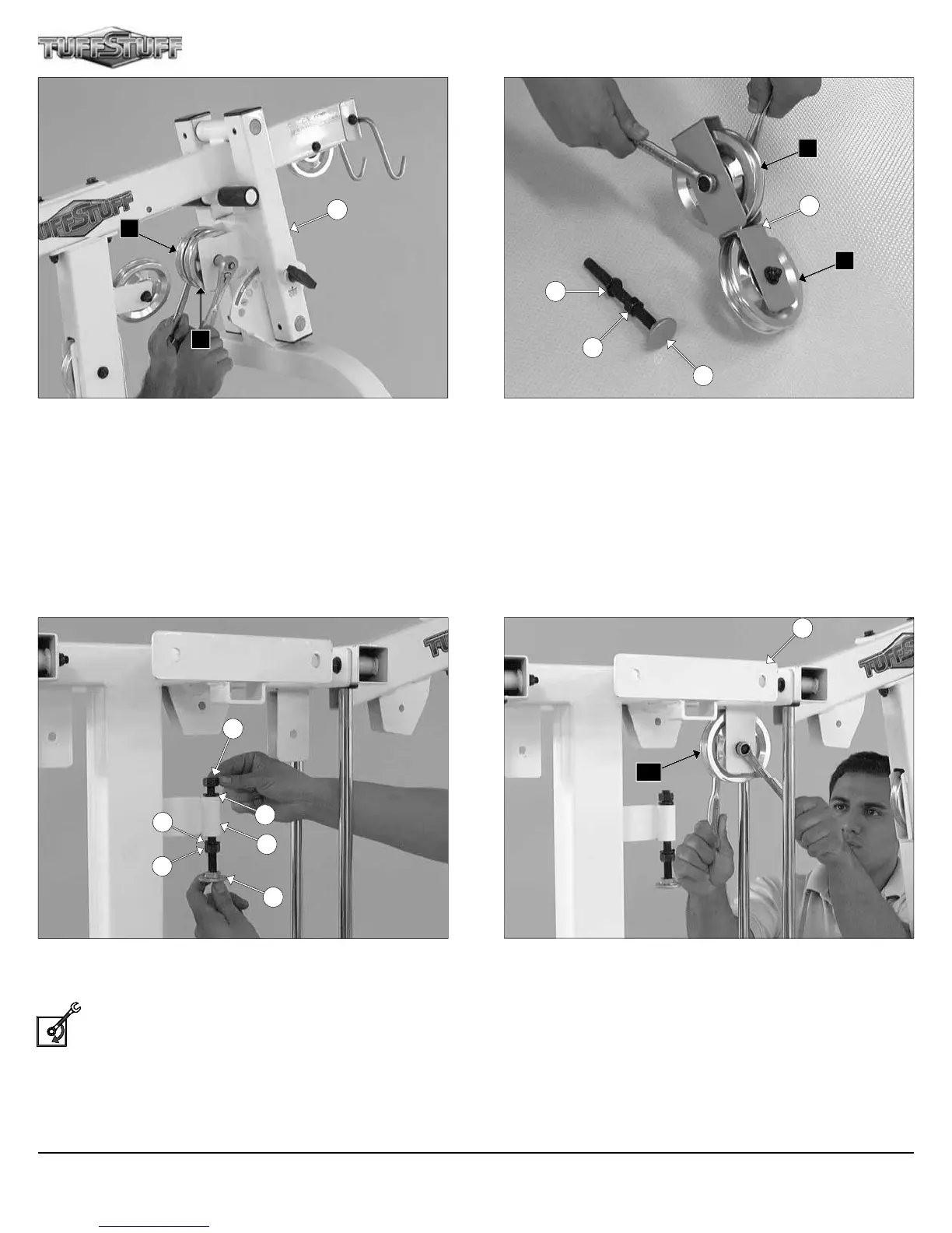
FIG. 25 Next, attach two Pulleys 4 1/2 Rd. (#67-Labeled A3, A5) to
the Press Bar Selector Housing (#41) using one Hex Head Cap
Screw 3/8-16 X 2 3/4 (#100), two Flat Washers SAE 3/8” (#93), and
one Nylon Insert Jam Lock Nut 3/8-16 (#118).
FIG. 26 Locate the Closed-end Double Pulley Bracket (#12) and
attach two Pulleys 4 1/2 Rd. (#67-Labeled A9, B4) using two Hex Head
Cap Screws 3/8-16 X 1 3/4 (#97), four Flat Washers SAE 3/8” (#93),
and two Nylon Insert Jam Lock Nuts 3/8-16 (#118). Next, thread one
Finished Hex Nut 1/2-13 (#88) and insert one Split Lock Washer
1/2” (#153) onto the Adjustable Stopper (#30).
41
A3
A5
12
30
88
153
A9
B4
FIG. 27 Next, attach the Adjustable Stopper (#30) to the receptacle
of the Weight Stack Frame (#53) using one Split Lock Washer
1/2” (#153) and one Finished Hex Nut 1/2-13 (#88).
Loosely Fasten: Do not completely fasten this hardware as-
sembly at this time, as it will be completely fasten once the ca-
bles have been adjusted.
FIG. 28 Next, attach a Pulley 4 1/2 Rd. (#67-Labeled A10) to the
Weight Stack Frame (#53) using one Hex Head Cap Screw 3/8-16 X 1
3/4 (#97), two Flat Washers SAE 3/8” (#93), and one Nylon Insert Jam
Lock Nut 3/8-16 (#118).
88
153
53
30
88
153
1
A10
Apollo Modular Gym System (Base Unit)