8
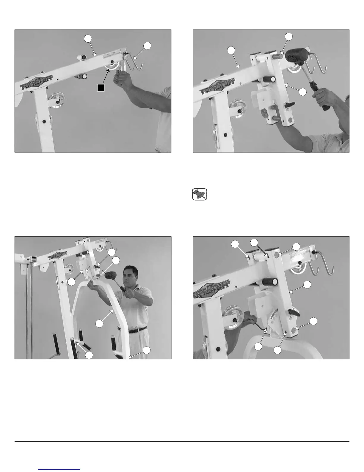
FIG. 21 Next, attach a Pulley 4 1/2 Rd (#67-Labeled A1) to the Top
Pulley Assembly (#49) using one Hex Head Cap Screw 3/8-16 X 2 1/2
(#99), two Flat Washers SAE 3/8” (#93), and one Nylon Insert Jam
Lock Nut 3/8-16 (#118). Next, attach the Lat Bar Holder 2 X 3 (#21) to
the Top Pulley Assembly (#49) using one Hex Head Cap Screw 3/8-
16 X 2 3/4 (#100), two Flat Washers SAE 3/8” (#93), and one Nylon
Insert Jam Lock Nut 3/8-16 (#118).
FIG. 22 Using a rubber mallet, insert one Pivot Axle 1 X 8 1/8 (#39)
through the holes of the Press Bar Selector Housing (#41) and
through the receptacle of the Top Pulley Assembly (#49) until the
Pivot Axle 1 X 8 1/8 (#39) is flush with both sides of the Press Bar
Selector Housing (#41).
Note: It is recommended to grease the Pivot Axles 1 X 8 1/8
(#39) with multi-purpose grease prior to assembling.
21
A1
49
49
39
41
Assembly Instructions
FIG. 23 Using a rubber mallet, insert two Plastic Insert Caps 2” Sq.
(#126) into the tube-ends of the Press Bar (#42). Next, insert the
Press Bar (#42) up into the Press Bar Selector Housing (#41) and
support in into place using the Pull Pin 1/2 X 3 1/2 (#130). Next, using
a rubber mallet, insert the Pivot Axle 1 X 8 1/8 (#39) into the Press
Bar Selector Housing (#41) and through the Press Bar (#42).
FIG. 24 Secure the two Pivot Axles 1 X 8 1/8 (#39) to the Press Bar
Selector Housing (#41) using four Set Screws 3/8-16 X 1/2 (#150).
Use the Supplied Hex Key 3/16” (#107) for securing these Set Screws
3/8-16 X 1/2 (#150) into the threaded sockets on the Press Bar
Selector Housing (#41). Next, clean the ends of the Pivot Axles 1 X
8 1/8 (#39) and apply four 1” Rd. Silver Mylar Decals (#77–Not shown).
These decals are used to hide and protect the ends of the axles.
39
42
150
150
39
39
150
150
41
126
126
41
130
Apollo Modular Gym System (Base Unit)