12
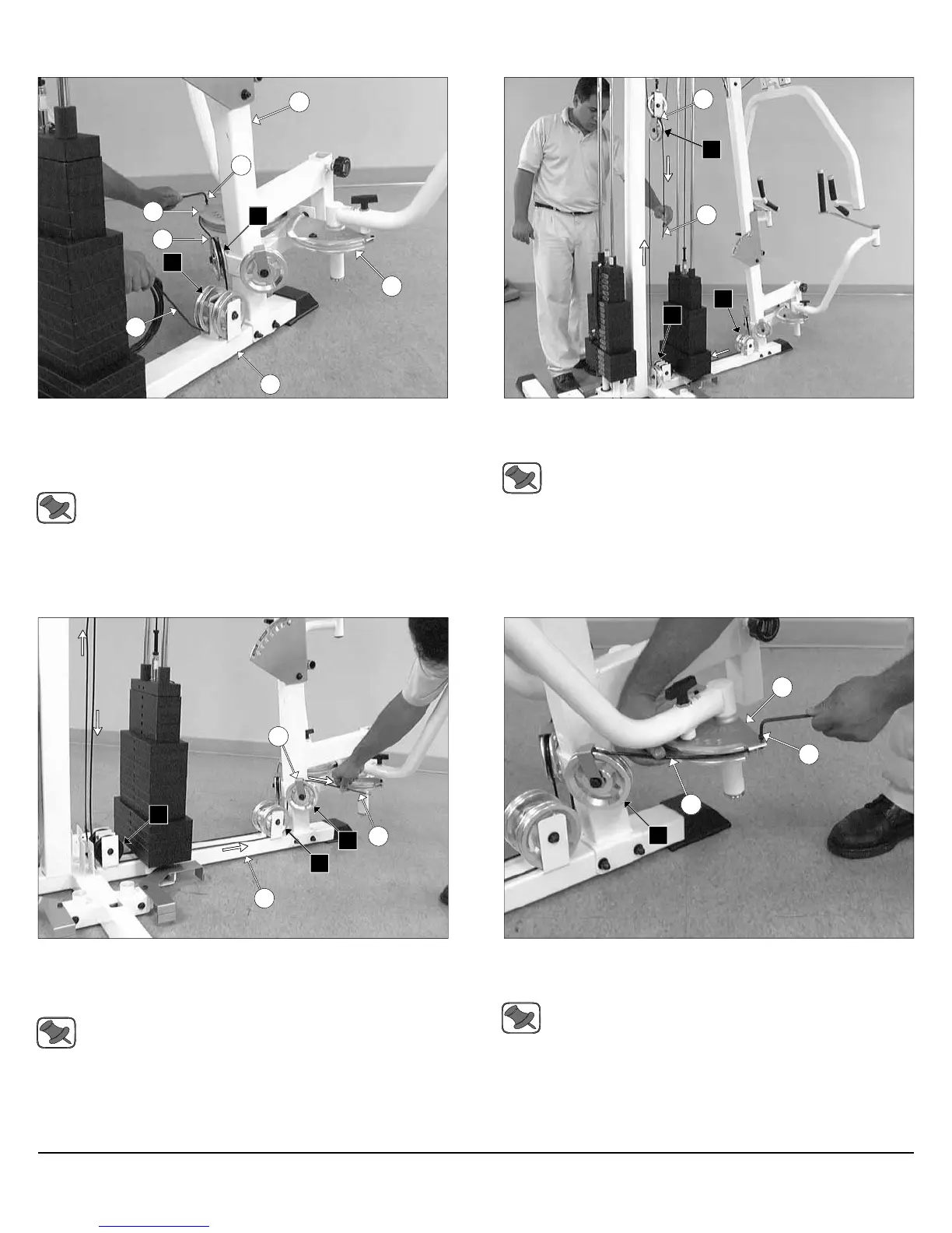
FIG. 37 Attach one end of the Pec Dec Cable (#37) to the Alumi-
num Cam Plate (#60) and secure it onto place using one Socket Head
Cap Screw 1/4-20 X 3/4 (#146). Next, route the Pec Dec Cable (#37)
over the Pulley 4 1/2 Rd. (#67-Labeled B1), and then under the Pulley 4
1/2 Rd. (#67-Labeled B2).
Note: Refer to Fig. C on fold-out page 21 for further clarification
of this hardware assembly.
FIG. 38 Continue routing the Pec Dec Cable (#37) under the weight
stack and the Pulley 3 1/2” Rd. (#66-Labeled B3), and then up and over
the Pulley 4 1/2” Rd. (#67-Labeled B4).
Note: Refer to the Cable Mapping Diagram on fold-out page 21
for further detailed illustration of the Pec Dec Cable (#37)
routing.
16
146
60
37
8
60
B2
B1
7
12
37
B3
B2
B4
Assembly Instructions
FIG. 39 Route the Pec Dec Cable (#37) down and under the Pulley
3 1/2” Rd. (#66-Labeled B5). Next, route the cable to the Pulley 4 1/2”
Rd. (#67-Labeled B6), and then up and over the Pulley 4 1/2” Rd. (#67-
Labeled B7).
Note: Refer to the Cable Mapping Diagram on fold-out page 21
for further detailed illustration of the Pec Dec Cable (#37)
routing.
FIG. 40 Next, attach the end of the Pec Dec Cable (#37) to the Alu-
minum Cam Plate (#30) and secure it into place using one Socket
Head Cap Screw 1/4-20 X 3/4 (#146).
Note: Refer to Fig. C on fold-out page 21 for further clarification
of this hardware assembly.
7
B5
137
8
B6
B7
37
60
146
B7
Apollo Modular Gym System (Base Unit)