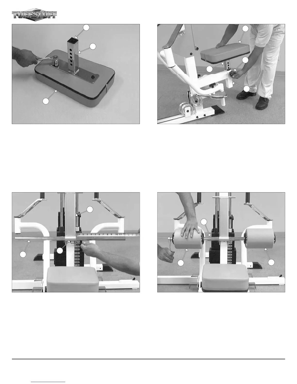
FIG. 41 Using a rubber mallet, insert one Plastic Insert Cap 1 3/4
(#123) into the tube-end of the Bench Press Adjustable Seat Frame
(#4). Next, attach the Bench Press Adjustable Seat Frame (#4) to
the Bench Press Seat Pad (#6) using two Hex Head Cap Screws 3/8-
16 X 1 1/4 (#96), and two Flat Washers SAE 3/8” (#93).
FIG. 42 Attach the assembled Bench Press Adjustable Seat
Frame (#4) to the Front Upright (#16).
4
6
123
16
6
4
156
13
FIG. 43 Next, insert the Foot Roll Tube 1 X 27 (#15) into the
receptacle of the Adjustable Back Pad Bracket (#2). Use a measur-
ing tape to center the Foot Roll Tube 1 X 27 (#15) to the Adjustable
Back Pad Bracket (#2). Next, secure the Foot Roll Tube 1 X 27 (#15)
to the Adjustable Back Pad Bracket (#2) using one Set Screw 1/4-20
X 1/4 (#147).
FIG. 44 Insert two Foam Rolls 1 X 5 1/2 X 7 1/4 (#13) to the tube-
ends of the Foot Roll Tube 1 X 27 (#15) and secure them into place
using two Button Head Socket Cap Screws 3/8-16 X 1 (#71), two Split
Lock Washers 3/8” (#152), and two Chrome Washers 3/8 X 1 1/2 (#74).
15
2
147
15
13
13
Apollo Modular Gym System (Base Unit)