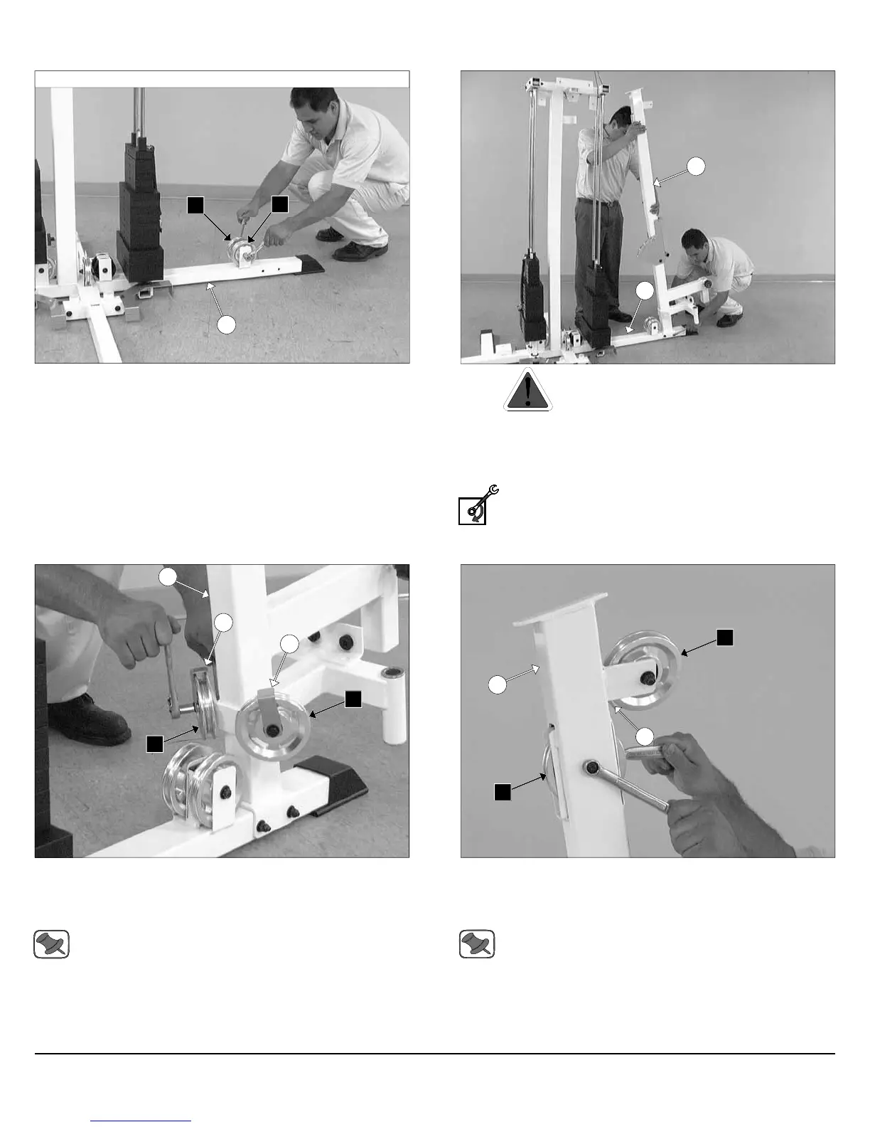
FIG. 13 Attach two Pulleys 4 1/2 Rd. (#67-Labeled B2, B6) to the
Press Bar Station Base Frame (#7) pulley brackets using one Hex
Head Cap Screw 3/8-16 X 4 (#103), two Flat Washers SAE 3/8 (#93),
and one Nylon Insert Jam Lock Nut 3/8-16 (#118).
FIG. 15 Attach two Pulleys 4 1/2 Rd (#67-Labeled B1, B7) and two
Cable Retainer Brackets (#8) to the Front Upright (#16) using two
Hex Head Cap Screws 3/8-16 X 2 (#98), four Flat Washers SAE
3/8” (#93), and two Nylon Insert Lock Nuts 3/8-16 (#119).
Note: Be sure the Cable Retainer Brackets (#8) are positioned
as shown above.
FIG. 14 Caution: It is strongly recommended to use another
person in assisting with this assembly.
Attach the Front Upright (#16) to the Bottom Connector Press Bar/
Pec Fly (#7) using two Hex Head Cap Screws 3/8-16 X 4 1/4 (#104),
four Flat Washers SAE 3/8” (#93), and two Nylon Insert Lock Nuts 3/8-
16 (#119).
Loosely Fasten: Do not completely fasten this hardware
assembly until assembling the Top Pulley Assembly (#49) to
the Press Bar Station Guide Rod Retainer (#18) described in
FIG. 18.
FIG. 16 Next, attach a Pulley 4 1/2 Rd (#67-Labeled A4) and a Ca-
ble Retainer Bracket (#8) to the plate of the Front Upright (#16) using
one Hex Head Cap Screw 3/8-16 X 2 (#98), two Flat Washers SAE
3/8” (#93), and one Nylon Insert Lock Nut 3/8-16 (#119).
Note: Be sure the Cable Retainer Bracket (#8) is positioned as
shown above.
Next, attach another Pulley 4 1/2 Rd (#67-Labeled A6) to the Front Up-
right (#16) using one Hex Head Cap Screw 3/8-16 X 2 1/2 (#99), two
Flat Washers SAE 3/8” (#93), and one Nylon Insert Jam Lock Nut 3/8-
16 (#118).
7
B2
Assembly of the Press Bar Station Fig. 13 - Fig. 48
B6
16
7
8
8
16
B7
B1
16
A4
A6
8
6
Assembly Instructions
Apollo Modular Gym System (Base Unit)