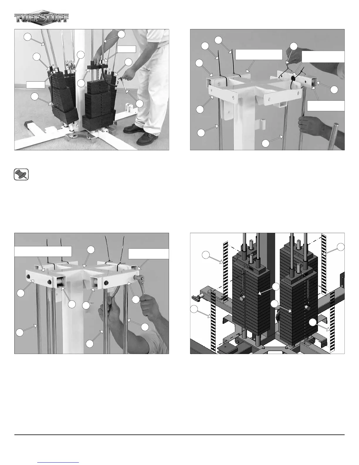
FIG. 9 Assemble each Top Plate/Selector Bar (#58) to its corre-
sponding workstation
Note: Be sure the Label and the Selector Pin w/Coil (#31) lo-
cated on each Top Plate/Selector Bar (#58) are facing out, be-
fore sliding the Top Plate/Selector Bars (#58) onto the Guide
Rods (#10).
FIG. 11 On the side of the Leg Extension/Curl Station, maneuver the
two Guide Rods (#10) into the bottom holes of a Guide Rod Retainer
(#17). Next, secure the Guide Rod Retainer (#17) to the Weight
Stack Frame (#53) using one Reinforcement Plate 1/4 X 2 X 8 1/2
(#43), two Hex Head Cap Screws 3/8-16 X 3 1/4 (#101), four Flat
Washers SAE 3/8” (#93), and two Nylon Insert Lock Nuts 3/8-16
(#119).
Next, repeat the same procedure for the Leg Press Station.
FIG. 10 On the Single Column Station, maneuver the two Guide
Rods (#10) into the bottom holes of a Guide Rod Retainer (#17).
Next, temporary secure the Guide Rod Retainer (#17) to the Weight
Stack Frame (#53) using two Plastic Ties (#127).
Next, locate the Press Bar Station Guide Rod Retainer (#18) and at-
tach it to the side of the Press Bar Station following the previous proce-
dure.
FIG. 12 Attach the Decal Weight Numbers (#85) to the Weight
Plates (#56).
58
31
58
10
31
10
18
127
127
127
17
Single Column Station
Press Bar Station
Lat Cable will route
through this hole
10
10
53
10
10
43
10
17
43
17
53
Leg Press Station
85
56
85
56
85
5
58
58
LABEL
LABEL
Leg Extension/Curl Station
Apollo Modular Gym System (Base Unit)
85