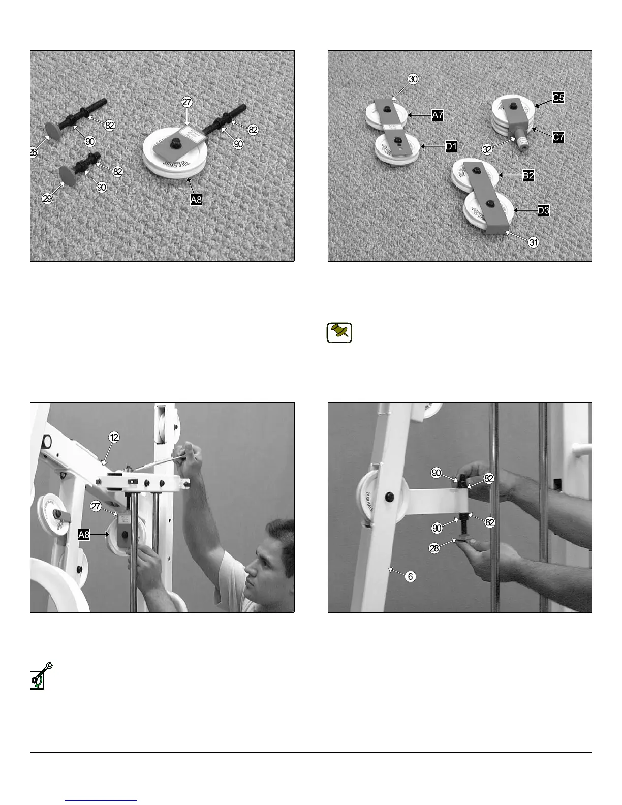
IG. 32 First, locate the Adjustable Pulley Bracket (#27) and insert
ne Nylon Pulley 4 1/2 Rd. (#67-Labeled A8). Secure the Nylon Pulley 4
2 Rd. (#67-Labeled A8) into place using one Hex Head Cap Screws 3/8-
X 1 3/4 (#102), two Flat Washers SAE 3/8” (#87), and one Nylon Insert
m Lock Nut 3/8-16 (#93). Next, thread one Regular Hex Nut 1/2-13
90), and insert one Split Washer B/O 1/2” (#82) over the bolt on the
djustable Pulley Bracket (#27), as shown above. Second, locate the
o Adjustable Stoppers (#28, #29) and thread one Regular Hex Nut
2-13 (#90), and insert one Split Washer B/O 1/2” (#82) over each bolt,
shown above.
IG. 34 Insert the welded bolt of the Adjustable Pulley Bracket (#27)
rough the hole located on the Top Pulley Assembly (#12) and secure it
to place at the top using one Flat Washer SAE 1/2” (#86), and one Nylon
sert Lock Nut 1/2-13 (#91).
Loosely Fasten: Do not completely fasten this hardware assem-
bly at this time, as it will be completely fastened later in the as-
sembly process.
FIG. 35 Insert (from bottom to top) the Long Adjustable Stopp
(#28) into the receptacle of the Front Upright (#6) and secure it into pla
using one Split Washer B.O. 1/2” (#82), and one Regular Hex Nut 1/2-1
(#90), as shown above. Loosely fasten the Regular Hex Nuts 1/2-1
(#84) to allow adjustment for cables tension later in the assembly proces
S-1000 Home Gym w/Adjustable High-Low Pulley System 10
wner
s
anua
:
ssem
y
nstruct
on
FIG. 33 Locate the Closed-End Adj. Double Pulley Bracket (#30), a
the Closed-End Double Pulley Bracket (#31). Then, attach four Nylo
Pulleys 4 1/2 Rd. (#67-Labeled D3,B2,D1,A7). Secure them into pla
using four Hex Head Cap Screws 3/8-16 X 1 3/4 (#102), eight Fl
Washers SAE 3/8” (#87), and four Nylon Insert Jam Lock Nuts 3/8-1
(#93).
Note: The four holes on the Closed-End Adj. Double Pulle
Bracket (#30) are used to adjust the cable tension once the cab
routing has been completed.
Next, locate the Floating Double Pulley Bracket (#32), shown above
the right, and attach two Nylon Pulleys 4 1/2 Rd. (#67-Labeled C7,C5
Secure the pulleys into place using one Hex Head Cap Screw 3/8-16 X
3/4 (#100), two Flat Washers SAE 3/8” (#87) and one Nylon Insert Ja
Lock Nut 3/8-16 (#93).
NOTE:
SELY FASTEN