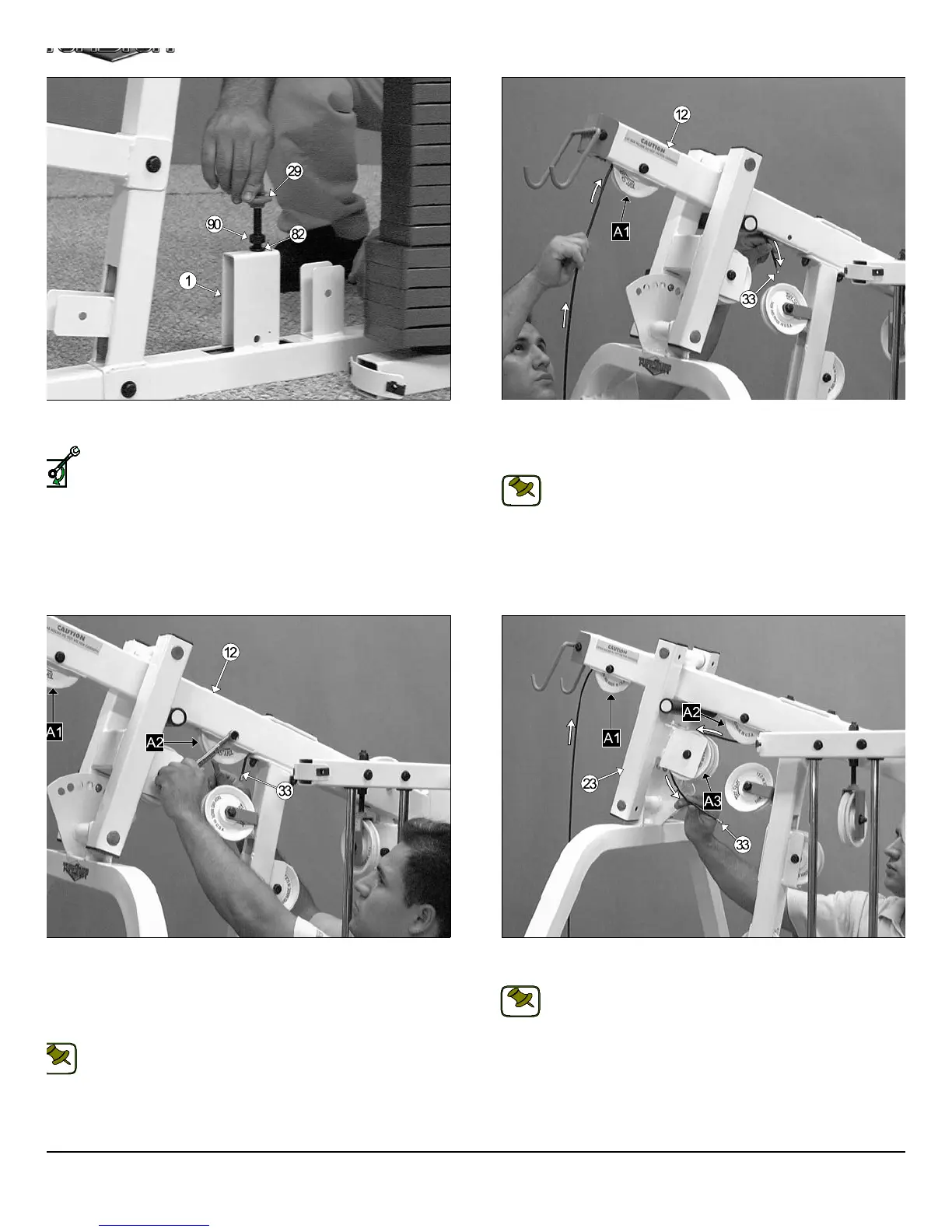
IG. 36 Thread the Short Adjustable Stopper (#29) into the threaded
cket on the Base Frame (#1), as shown above.
Loosely Fasten: Do not completely fasten this hardware assem-
bly at this time, as it will be completely fastened later in the as-
sembly process.
FIG. 37 Begin routing the Lat Cable (#33) up and over the Nyl
Pulley 4 1/2 Rd. (#67-Labeled A1) and into the tube of the Top Pulle
Assembly (#12). Then, pull the Lat Cable (#33) down through the ope
ing at the bottom of the Top Pulley Assembly (#12).
Note: Refer to the Cable Mapping Diagram on page 24 for furth
detailed illustration of the Lat Cable (#33) routing.
IG. 38 Insert a Nylon Pulley 4 1/2 Rd. (#67-Labeled A1) into the slot
the bottom of the Top Pulley assembly (#12) and secure it into place
ing one Hex Head Cap Screw 3/8-16 X 2 1/2 (#101), two Flat Washers
AE 3/8” (#87), and one Nylon Insert Jam Lock Nut 3/8-16 (#93). Be sure
e cable is routed properly into the groove on the Nylon Pulley 4 1/2 Rd.
67-Labeled A1).
Note: Refer to the Cable Mapping Diagram on page 24 for further
detailed illustration of the Lat Cable (#33) routing.
FIG. 39 Next, route the Lat Cable (#33) over the Nylon Pulley 4-1/2 R
(#67-Labeled A3).
Note: Refer to the Cable Mapping Diagram on page 24 for furth
detailed illustration of the Lat Cable (#33) routing.
11
TS-1000 Home Gym w/Adjustable High-Low Pulley Syste
SELY FASTEN
NOTE:
NOTE:
NOTE: