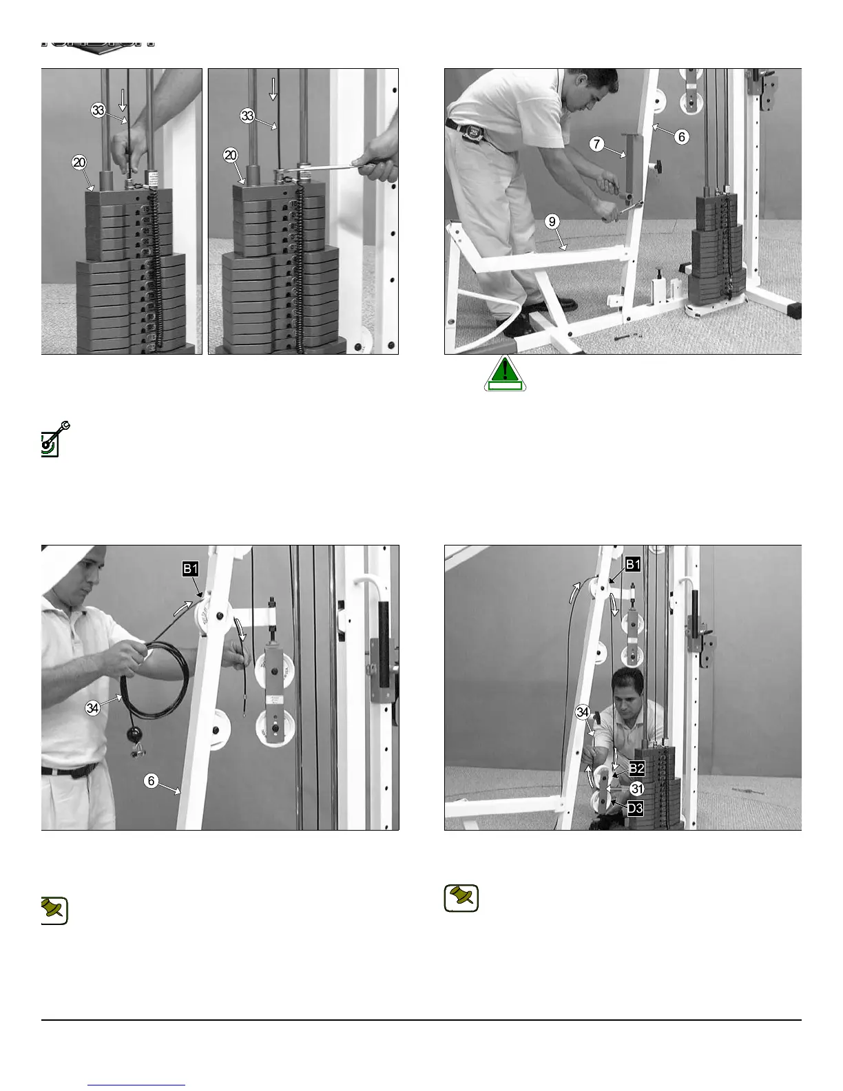
IG. 46 Remove the hardware from one end of the Leg Extension/
bdominal Cable (#34). Next, begin routing the Leg Extension/
bdominal Cable (#34) through the opening of the Front Upright (#6)
nd over the Nylon Pulley 4 1/2 Rd. (#67-Labeled B1).
Note: Refer to the Cable Mapping Diagram on page 25 for further
detailed illustration of the Leg Extension/Abdominal Cable (#34)
routing.
FIG. 47 Next, route the Leg Extension/Abdominal Cable (#3
through the Closed-end Double Pulley Bracket (#31) and under th
Nylon Pulley 4 1/2 Rd. (#67-Labeled B2), as shown above.
Note: Refer to the Cable Mapping Diagram on page 25 for furth
detailed illustration of the Leg Extension/Abdominal Cable (#3
routing.
IG. 44 Next, attach the Lat Cable (#33) to the Top Plate/ Selector
ar (#20) and secure it into place using one Split Bolt 1/2-13 x 1 (#85),
nd one Split Washer Z/P 1/2” (#83). Refer to Fig. B on page 24 for
rther illustration of this hardware assembly.
Fully Fasten: Proceed to fully fasten this hardware assembly.
FIG. 45 Before beginning routing the Leg Extension/Abdomin
Cable (#34) it is necessary to remove the Adjustabl
Back Pad Bracket (#7) and the Hardware that connec
the Leg Extension Bench Frame (#9) to the Front Up Right (#6). Th
is done to ensure the Leg Extension/Abdominal Cable (#34) be proper
routed. Otherwise the Cable will get tangled between the bolts that hol
these assemblies.
13
TS-1000 Home Gym w/Adjustable High-Low Pulley Syste
LY FASTEN
CAUTION
NOTE:
NOTE: