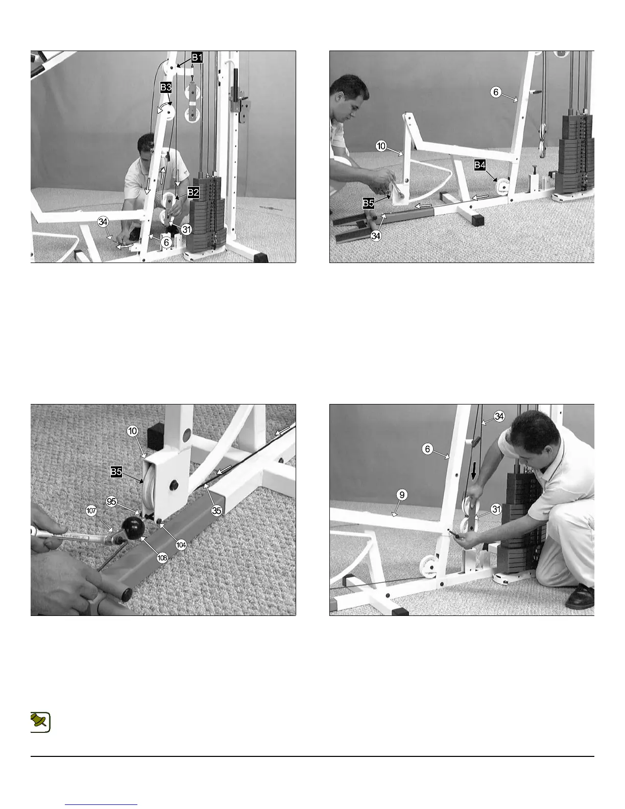
IG. 50 Route the Leg Extension/Abdominal Cable (#34) up to the
eg Extension Arm (#10). Then, affix a Nylon Ball 1 3/4 x 5/16 (#108),
nd a Strap Bracket #20 (#107) to the cable end. Lock them into place
ing a Shoulder Bolt 3/8 x 3/4 (#106), and a Nylon Insert Lock Nut 5/16-
(#94).
Next, secure the Leg Extension/Abdominal Cable (#34) to the
eg Extension Arm (#10) using one Hex Head Cap Screw 1/4-20 (#104),
nd one Nylon Insert Lock Nut 1/4-20 (#95). Refer to Fig. C on page 25
r further illustration of this hardware assembly.
Note: Refer to the Cable Mapping Diagram on page 25 for further
detailed illustration of the Leg Extension/Abdominal Cable (#34)
routing.
FIG. 51 Press down the Closed-End Double Pulley Bracket (#31) t
apply tension to the Leg Extension/Abdominal Cable (#34). Then, r
attach the Leg Extension Bench Frame (#9) to the Front Upright (#
using the previously removed Hardware (one Hex Head Cap Screw 3/8-1
x 2 3/4 (#100), two Flat Washers SAE 3/8” (#87), and one Nylon Inse
Jam Lock Nut 3/8-16 (#93).
IG. 48 Continue to route the Leg Extension/Abdominal Cable (#34)
p and over the Nylon Pulley 4 1/2 Rd. (#67-Labeled B3), then down into
e Front Upright’s (#6) tube. Next, pull the Leg Extension/Abdominal
able (#34) through the opening at the bottom of the Front Upright (#6).
ote: Refer to the Cable Mapping Diagram on page 25 for further detailed
ustration of the Leg Extension/Abdominal Cable (#34)routing.
FIG. 49 Insert two Nylon Pulleys 4 1/2 Rd. (#67-Labeled B4), one to th
bottom pulley bracket of the Front Upright (#6) and the other to the pull
bracket of the Leg Extension Arm (#10). Secure them into place usin
two Hex Head Cap Screws 3/8-16 x 1 3/4 (#102), four Flat Washers SA
3/8” (#87), and two Nylon Insert Jam Lock Nuts 3/8-16 (#93).
S-1000 Home Gym w/Adjustable High-Low Pulley System 14
wner
s
anua
:
ssem
y
nstruct
on
NOTE: