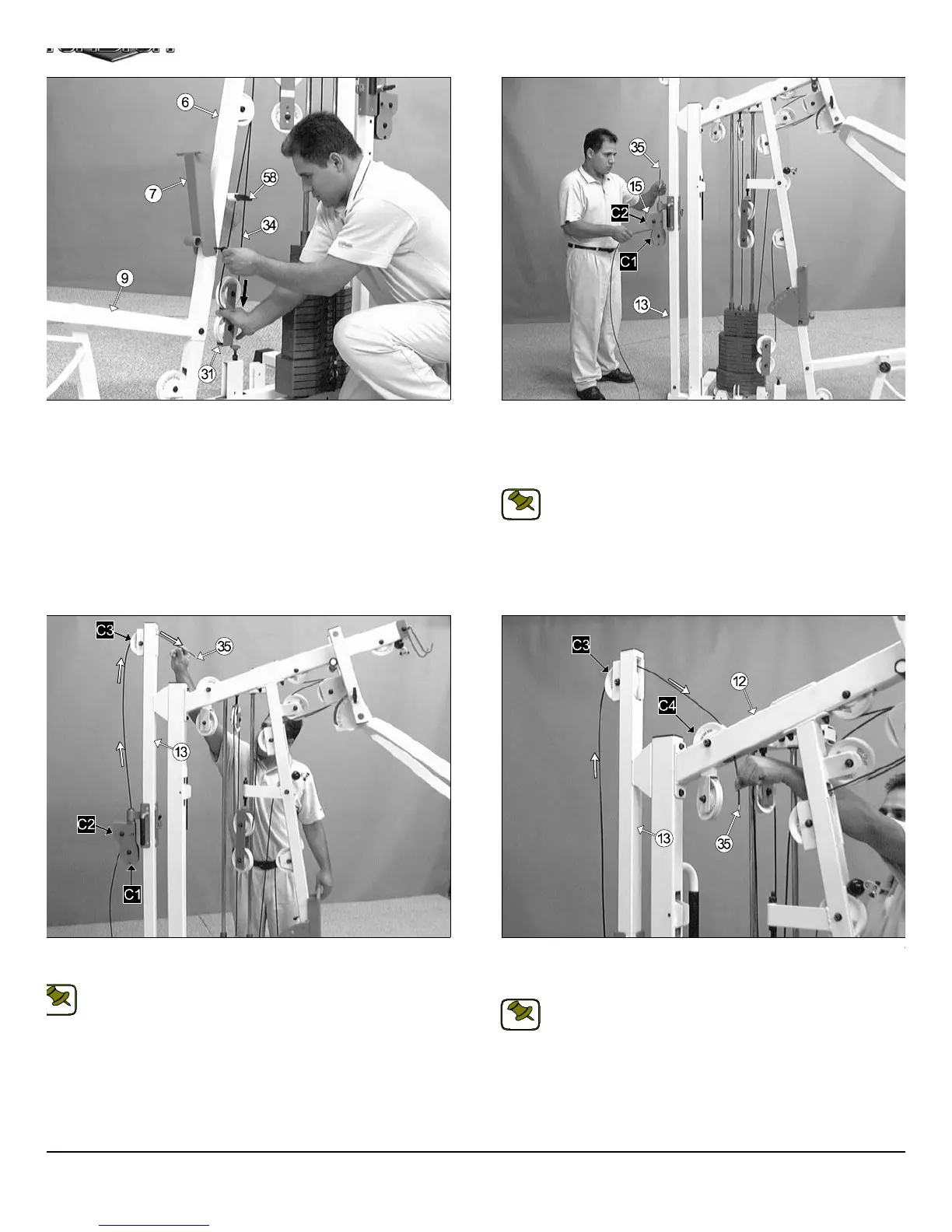
IG. 54 Route the High-Low Cable (#35) up and over the Nylon Pulley
1/2 Rd. (#67-Labeled C3)
Note: Refer to the Cable Mapping Diagram on page 26 for further
detailed illustration of the High-Low Cable (#35) routing.
FIG. 55 Route the High-Low Cable (#35) down to the Nylon Pulley
1/2 Rd. (#67-Labeled C4) passing through the opening of the Top Pulle
Assembly (#12).
Note: Refer to the Cable Mapping Diagram on page 26 for furth
detailed illustration of the High-Low Cable (#35) routing.
IG. 52 Press down the Closed-End Double Pulley Bracket (#31) to
pply tension to the Leg Extension/Abdominal Cable (#34). Then, re-
tach the Adjustable Back Pad Bracket (#7) to the Front Upright (#6)
ing the previously removed Hardware (one Hex Head Cap Screw 3/8-16
3 1/4 (#99), two Flat Washers SAE 3/8” (#87), two Nylon Flat Washer
8” (#88), and one Nylon Insert Jam Lock Nut 3/8-16 (#93).
FIG. 53 Route the High-Low Cable (#35) between the two Nylon Pu
leys 3 1/2 Rd. (#68-Labeled C1, C2), then up between the Nylon Pulley
1/2 Rd. (#68-Labeled C2) and the Hex Head Cap Screw 1/4-20 x 1 1
(#104). Continue routing the cable up through the tube of the High-Lo
Double Pulley Bracket (#15).
Note: Refer to the Cable Mapping Diagram on page 26 for furth
detailed illustration of the High-Low Cable (#35) routing.
15
TS-1000 Home Gym w/Adjustable High-Low Pulley Syste
NOTE:
NOTE:
NOTE: